GENERAL INFORMATION
3
4. When the same servicing operation is applicable to several different units, the manual will direct you
to the appropriate page.
5. For the sake of brevity, self-explanatory removal and installation procedures are omitted.
More complex procedures are covered in detail.
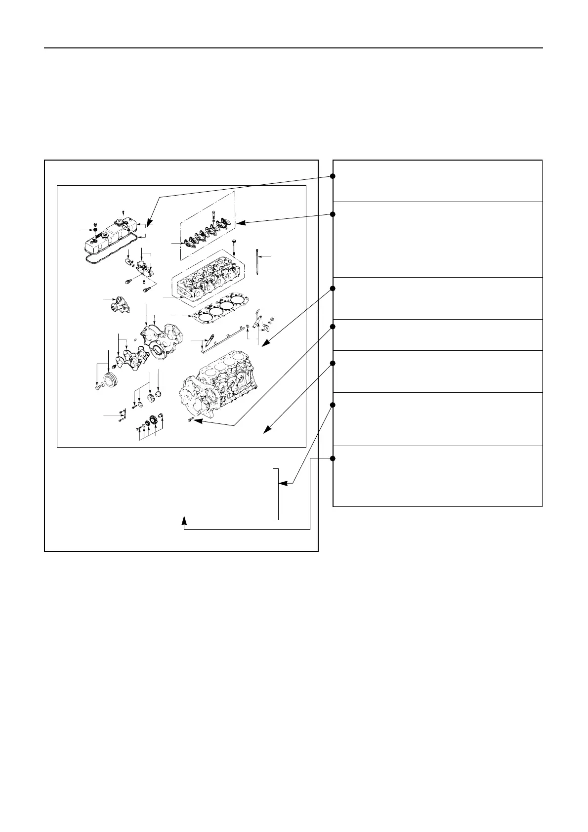
6. Each service operation section in this Workshop Manual begins with an exploded view of the
applicable area. A brief explanation of the notation used follows.
Disassembly Steps - 2
1. Water by-pass hose
2. Thermostat housing
3. Water pump
▲ 4. Injection nozzle holder
5. Glow plug and glow plug connector
6. Cylinder head cover
▲ 7. Rocker arm shaft and rocker arm
8. Push rod
▲ 9. Cylinder head
10. Cylinder head gasket
▲ 11. Crankshaft damper pulley with
dust seal
12. Timing gear case cover
13. Timing gear cover
14. Timing gear oil pipe
15. Idler gear “B” and shaft
▲ 16. Idler gear “A”
17. Idler gear shaft
Inverted Engine
Parts marked with an asterisk (*) are
included in the repair kit.
Parts within a square frame are to be
removed and installed as a single unit,
and their disassembly steps or reas-
sembly steps are shown in the
illustrations respectively.
The number tells you the service oper-
ation sequence.
Removal of unnumbered parts is unne-
cessary unless replacement is required.
The "* Repair Kit" indicates that a repair
kit is available.
The parts listed under "Disassembly
Steps" or "Reassembly Steps" are in the
service operation sequence.
The removal or installation of parts
marked with a triangle (▲ ) is an
important operation. Detailed infor-
mation is given in the text.
 Loading...


