CONNECTING ROD
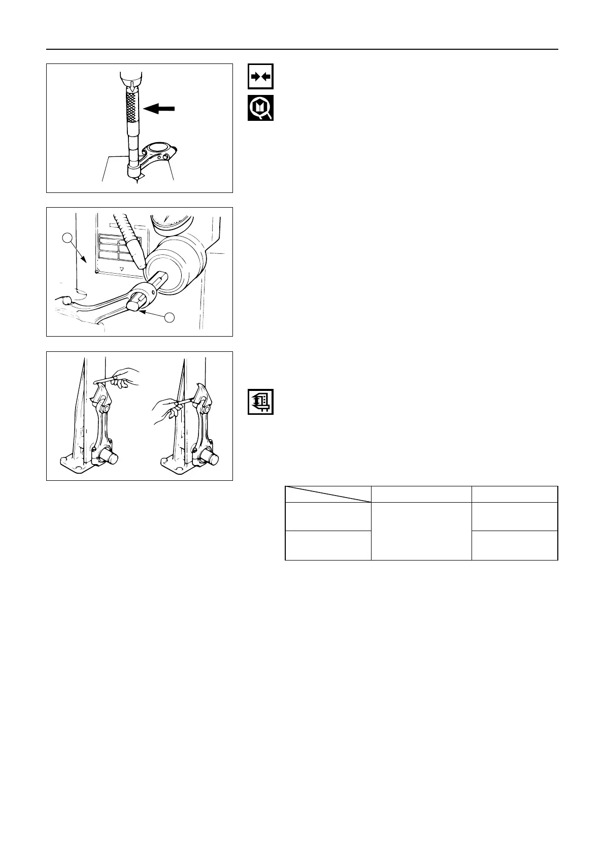
Connecting Rod Alignment
Use a connecting rod aligner to measure the distortion
and the parallelism between the connecting rod big end
hole and the connecting rod small end hole.
If either the measured distortion or parallelism exceed
the specified limit, the connecting rod must be replaced.
Connecting Rod Alignment
Per Length of 100 mm (3.94 in) mm(in)
Standard Limit
Distortion
0.20
0.05 or Less
(0.008)
(0.002)
0.15
Parallelism
(0.006)
ENGINE ASSEMBLY ( 2 )
Connecting Rod Bushing Installation
1. Clamp the connecting rod in a vice.
2. Use the connecting rod bushing installer to install
the connecting rod bushing.
Connecting Rod Bushing Replacer:
3. Use a piston pin hole grinder 1 fitted with a reamer
2 to ream the piston pin hole.
 Loading...


