5A–33
BRAKE CONTROL SYSTEM
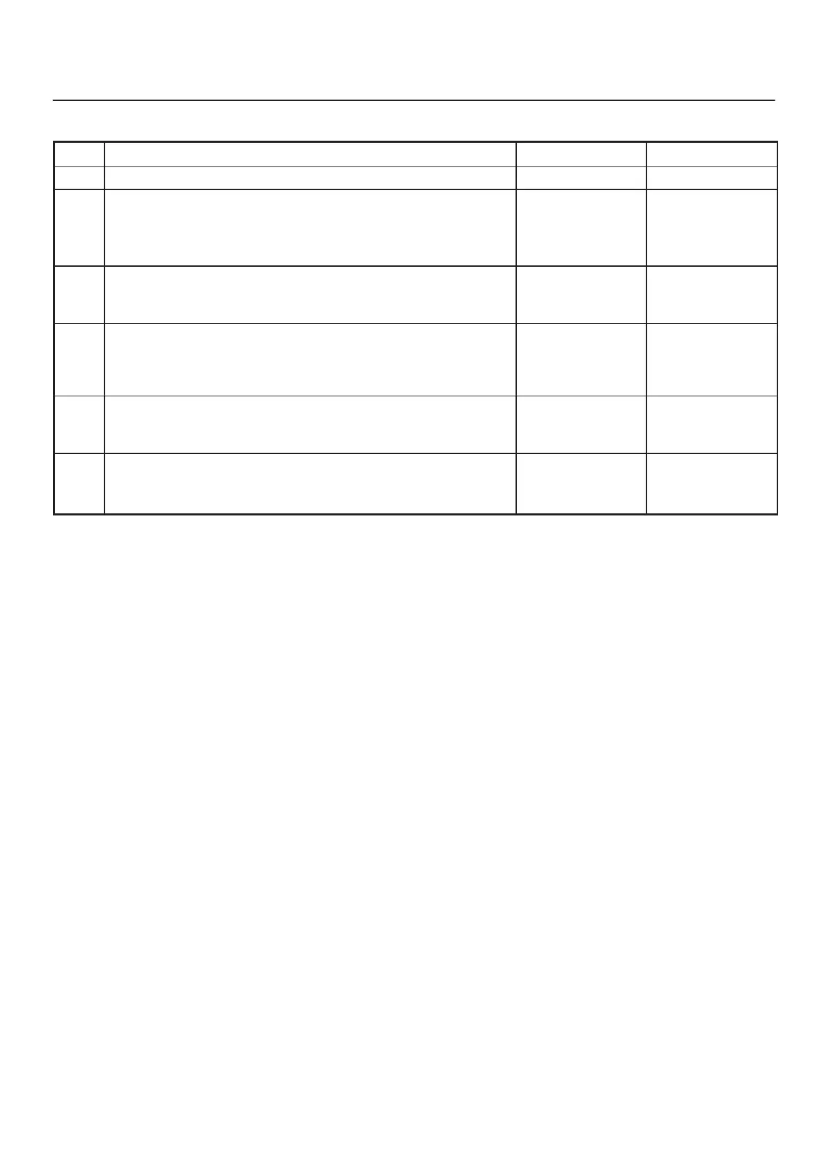
Chart A-4 Brake Pedal Feed Is Abnormal
Step
Action
Yes No
1 Is the stop light actuated when the brake pedal is depressed? Go to Step 2 Go to Step 3
2 1. Turn the ignition switch off.
2. Disconnected EHCU connector.
Is the check voltage EHCU connector terminals 13 to 7 when
brake pedal is depressed than battery voltage?
Go to Step 4
Harness NG
between brake
SW and EHCU.
Go to Step 6
3 Is stop light fuse normal?
Go to Step 5
Replace stop light
fuse.
Go to Step 6
4 Is the check continuity between EHCU connector terminals, 7 to
body grounded?
Go to Step 6
Repair body
grounded
harness.
Go to Step 6
5 Is brake SW normal? Repair stop light
harness.
Go to Step 6
Replace brake
SW.
Go to Step 6
6 Reconnect all components, ensure all components are properly
mounted.
Was this step finished?
Repeat the “Basic
diagnostic flow
chart”
Go to Step 6
 Loading...