5A–45
BRAKE CONTROL SYSTEM
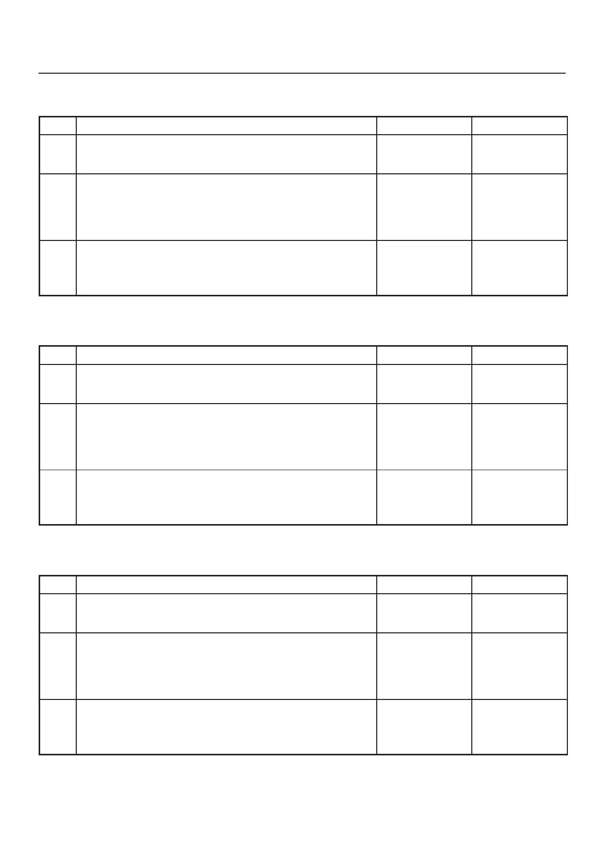
Chart B-13 FR Isolation Solenoid Coil Failure (DTC 43 (Flash out) / C0241, C0243 (Serial
communications))
Step
Action
Yes No
1 Was the “EHCU Connector Pin–out Checks” performed?
Go to Step 2
Go to “EHCU
Connector
Pin–out Checks.”
2 1. Turn the key switch to off.
2. Disconnect the 2–way EHCU connector (C–5) from the
EHCU.
3. Inspect the connector for damage or corrosion.
Is the connector free from damage or corrosion?
Go to Step 3
Repair the
connector.
Repeat the “Basic
Diagnostic Flow
Chart.”
3 1. Replace the Coil Integrated Module.
2. Reconnect all component, ensure all components are properly
mounted.
Was this step finished?
Repeat the “Basic
diagnostic flow
chart”
Go to Step 3
Chart B-14 FR Dump Solenoid Coil Failure (DTC 44(Flash out) / C0242, C0244 (Serial
communications))
Step
Action
Yes No
1 Was the “EHCU Connector Pin–out Checks” performed?
Go to Step 2
Go to “EHCU
Connector
Pin–out Checks.”
2 1. Turn the key switch to off.
2. Disconnect the 2–way EHCU connector (C–5) from the
EHCU.
3. Inspect the connector for damage or corrosion.
Is the connector free from damage or corrosion?
Go to Step 3
Repair the
connector.
Repeat the “Basic
Diagnostic Flow
Chart.”
3 1. Replace the Coil Integrated Module.
2. Reconnect all component, ensure all components are properly
mounted.
Was this step finished?
Repeat the “Basic
diagnostic flow
chart”
Go to Step 3
Chart B-15 Rear Isolation Solenoid Coil Failure (DTC 45 (Flash out) / C0251, C0253 (Serial
communications))
Step
Action
Yes No
1 Was the “EHCU Connector Pin–out Checks” performed?
Go to Step 2
Go to “EHCU
Connector
Pin–out Checks.”
2 1. Turn the key switch to off.
2. Disconnect the 2–way EHCU connector (C–5) from the
EHCU.
3. Inspect the connector for damage or corrosion.
Is the connector free from damage or corrosion?
Go to Step 3
Repair the
connector.
Repeat the “Basic
Diagnostic Flow
Chart.”
3 1. Replace the Coil Integrated Module.
2. Reconnect all component, ensure all components are properly
mounted.
Was this step finished?
Repeat the “Basic
diagnostic flow
chart”
Go to Step 3

 Loading...