5A–44
BRAKE CONTROL SYSTEM
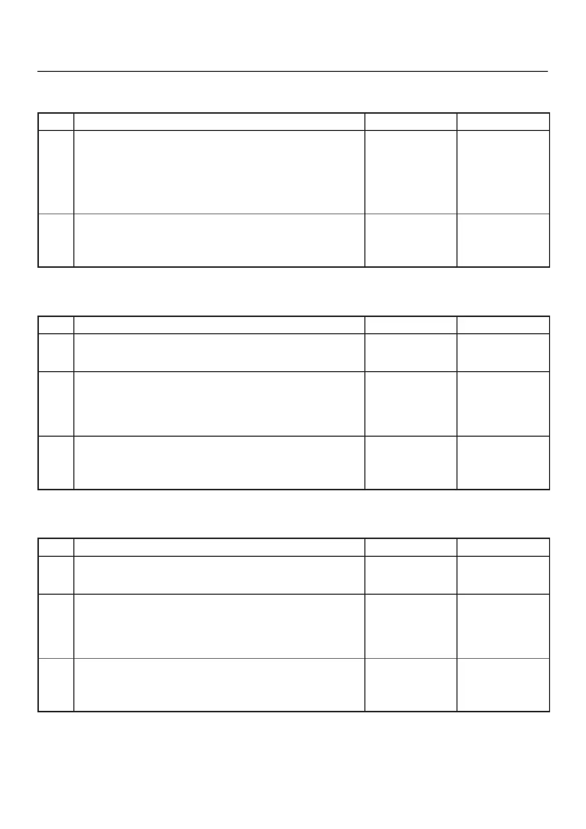
Chart B-10 EHCU Valve Relay Failure (DTC 35 (Flash out) / C0265, C0266 (Serial
communications))
Step
Action
Yes No
1 1. Turn the key off.
2. Disconnect coil integrated module connector.
3. Measure the voltage between terminal 1 of the coil integrated
module connector (C-5) and body ground.
Is the voltage equal to the battery voltage?
Replace EHCU.
Go to Step 2
Repair fuse and
harness coil
integrated
module connector
(C-5) terminal 1
and battery.
Go to Step 2
2 1. Reconnect all components, ensure all components are
properly mounted.
2. Clear diagnostic trouble code.
Was this step finished?
Repeat the “Basic
diagnostic flow
chart”
Go to Step 2
Chart B-11 FL Isolation Solenoid Coil Failure (DTC 41 (Flash out) / C0245, C0247 (Serial
communications))
Step
Action
Yes No
1 Was the “EHCU Connector Pin–out Checks” performed?
Go to Step 2
Go to “EHCU
Connector
Pin–out Checks.”
2 1. Turn the key switch to off.
2. Disconnect the 2–way EHCU connector (C–5) from the
EHCU.
3. Inspect the connector for damage or corrosion.
Is the connector free from damage or corrosion?
Go to Step 3
Repair the
connector.
Repeat the “Basic
Diagnostic Flow
Chart.”
3 1. Replace the Coil Integrated Module.
2. Reconnect all component, ensure all components are properly
mounted.
Was this step finished?
Repeat the “Basic
diagnostic flow
chart”
Go to Step 3
Chart B-12 FL Dump Solenoid Coil Failure (DTC 42 (Flash out) / C0246, C0248 (Serial
communications))
Step
Action
Yes No
1 Was the “EHCU Connector Pin–out Checks” performed?
Go to Step 2
Go to “EHCU
Connector
Pin–out Checks.”
2 1. Turn the key switch to off.
2. Disconnect the 2–way EHCU connector (C–5) from the
EHCU.
3. Inspect the connector for damage or corrosion.
Is the connector free from damage or corrosion?
Go to Step 3
Repair the
connector.
Repeat the “Basic
Diagnostic Flow
Chart.”
3 1. Replace the Coil Integrated Module.
2. Reconnect all component, ensure all components are properly
mounted.
Was this step finished?
Repeat the “Basic
diagnostic flow
chart”
Go to Step 3