5A–43
BRAKE CONTROL SYSTEM
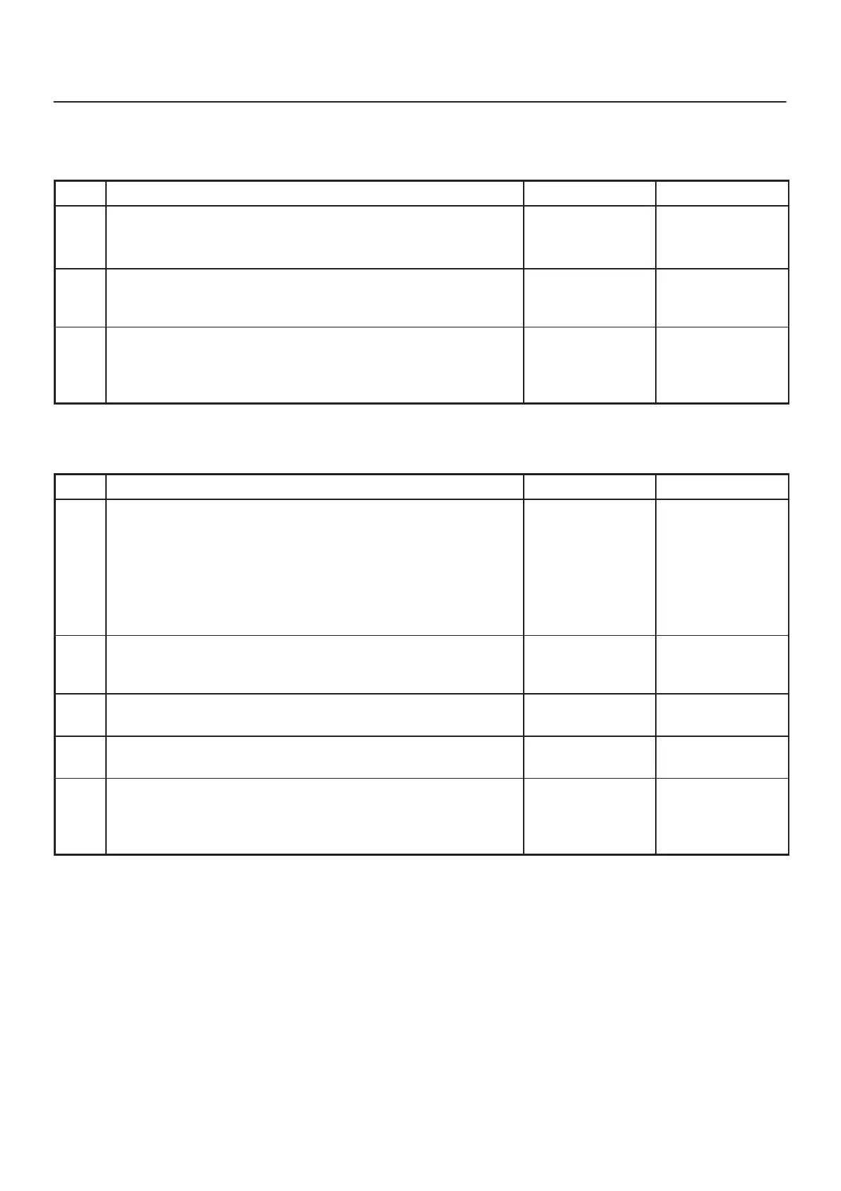
Chart B-8 2WD Controller in 4WD Vehicle Controller (DTC 13 (Flash out) / C0285 (Serial
communications)), 4WD State Input Signal Failure (DTC 24 (Flash out) / C0282 (Serial
communications))
Step
Action
Yes No
1 Remove coil integrated module connector.
Is the coil integrated module connector (C-4) terminal 8 line
normally?
Go to Step 2
Repair.
Go to Step 3
2 Is the 4WD controller normally?
Replace EHCU.
Go to Step 3
Replace 4WD
controller.
Go to Step 3
3 1. Reconnect all components, ensure all components are
properly mounted.
2. Clear diagnostic trouble code.
Was this step finished?
Repeat the “Basic
diagnostic flow
chart”
Go to Step 3
Chart B-9 Pump Motor Failure (DTC 32 (Flash out) / C0267, C0268 (Serial
communications))
Step
Action
Yes No
1 1. Turn the key off.
2. Disconnect coil integrated module connector.
3. Measure the voltage between terminal 1 of the coil integrated
module connector (C-5) and body ground.
Is the voltage equal to the battery voltage?
Go to Step 2
Repair
fuse/harness
between battery
and coil
integrated
module connector
(C-5) terminal 1.
Go to Step 5
2 Is the harness from the hydraulic unit connected to the coil
integrated module connector?
Go to Step 3
Connect to the
connector.
Go to Step 3
3 Is the harness from the hydraulic unit normally?
Go to Step 4
Replace EHCU.
Go to Step 5
4 Is the check resistance of hydraulic unit connector terminals 1 and
2 between 0.2 and 1.0 ohms?
Replace EHCU.
Go to Step 5
Replace EHCU.
Go to Step 5
5 1. Reconnect all components, ensure all components are
properly mounted.
2. Clear diagnostic trouble code.
Was this step finished?
Repeat the “Basic
diagnostic flow
chart”
Go to Step 5