EasyManua.ls Logo

iSystem iC5000 - 14-pin 2.54 mm Renesas RH850 Debug Adapter; RH850 Target Pinout; Fuse Protection

iSystem iC5000
69 pages
Print Icon
To Next Page IconTo Next Page
To Previous Page IconTo Previous Page
Loading...
iSYSTEM, October 2016 48/69
The following pinout is valid on the target side:
Signal direction
Signal
Pin
Pin
Signal
Signal direction
I
MSEO0
1
2
VTREF
I
MSEO1
3
4
TCK
O
GND
5
6
TMS
O
I
MDO0
7
8
TDI
O
I
MDO1
9
10
TDO
I
GND
11
12
nTRST
O
I
MDO2
13
14
NC
I
MDO3
15
16
EVTI
O
GND
17
18
EVTO
I
I
MCKO
19
20
RESET
I/O
I
MDO4
21
22
NC
O
GND
23
24
GND
I
MDO5
25
26
NC
I
MDO6
27
28
NC
GND
29
30
GND
I
MDO7
31
32
NC
I
MDO8
33
34
NC
GND
35
36
GND
I
MDO9
37
38
NC
I
MDO10
39
40
NC
GND
41
42
GND
I
MDO11
43
44
MDO13
I
I
MDO12
45
46
MDO14
I
GND
47
48
GND
I
MDO15
49
50
NC
MPC5xxx and SPC56 50-pin 16-bit Nexus target pinout
Blue colored signals are required for trace.
Note: 50-pin Samtec MPC5xxx Nexus 16-bit Cable Adapter features resettable fuses on pins 2, 4, 6, 8, 10, 12, 16
and 20. These protect debug signals against overcurrent and cycle back to a conductive state after the excessive
current fades away. All other signals are protected via 47 ohm serial resistor.
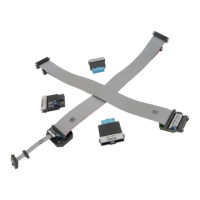
The adapter connects to the target via a 50-pin Samtec connector (SAMTEC ERM8-025-01-L-D-EM2). A target
should feature a matching part (for example SAMTEC - ERF8-025-05.0-L-DV in the SMT technology).

Other manuals for iSystem iC5000

Related product manuals