Note: This product is obsolete and is fully replaced with IC50163
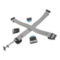
This adapter is used to connect the iC5000 development system to Infineon XC166, XC2000 or TriCore based
target. It connects to Debug/Trace module on one side and to the target debug connector on the other side. It can
be used for targets featuring 10-pin 1.27mm pitch target debug connector with Infineon DAP pinout.
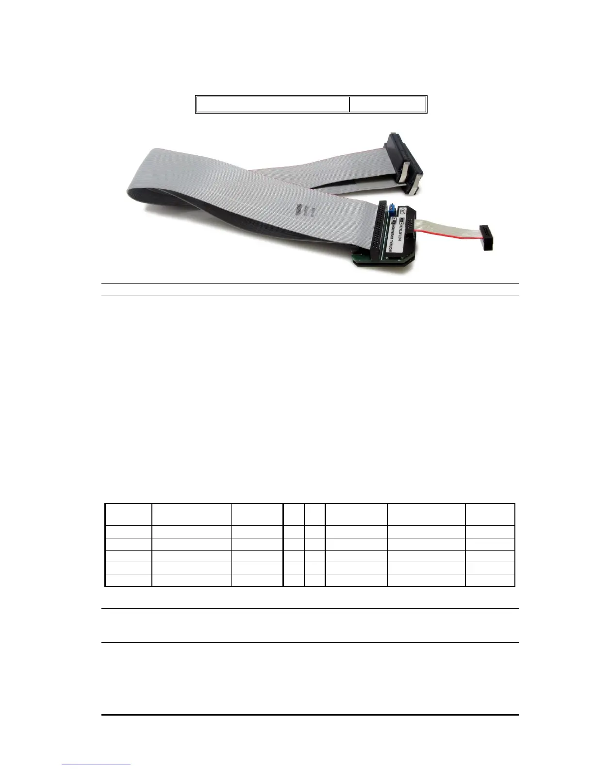
From Rev. E1 on, Infineon 3-pin DAP debug interface (Wide Mode) is supported (labeled “Infineon DAP2”).
Older revisions support 2-pin DAP (one clock line + one bidirectional data line) interface only (labeled “Infineon
DAP”).
From Rev. D1 on, Hot Attach operation without connecting/disconnecting the adapter from the target is
supported. Rev. D1 newly introduces jumper J1.
With jumper J1 in position 1-2 (default), normal debug operation is configured. The debugger drives MCU reset
line low during the initial debug connection and then takes control over the microcontroller.
With jumper J1 in position 2-3, Hot Attach operation is configured. In this case, all debug signals from the
iC5000 unit are disconnected and the target starts running as soon as the power is applied to the target. When
Hot Attach command is issued from winIDEA, the debugger connects to the MCU and control over the MCU is
taken without resetting the MCU. Depending on the target MCU, refer to the XC166/XC2000 or the TriCore
technical notes document for more details on Hot Attach configuration and use.
The following pinout is valid on the target side:
10-pin Infineon DAP pinout
Note: 10-pin 1.27mm Infineon DAP Cable Adapter features resettable fuses on pins 1, 2, 3, 4, 5, 6, 8, 9 and 10.
These fuses protect debug signals against overcurrent and cycle back to a conductive state after the excessive
current fades away.
The adapter connects to the target via a 10-pin 1.27mm connector (for example SAMTEC: FFSD-05-01-N). A
target should feature a matching part (for example SAMTEC: SHF-105-01-L-D-TH).
 Loading...