Function and Features
Copyright© Itech Electronics Co., Ltd. 45
Note
Please make sure the trigger source is selected in MANUAL item in above
operations (refer to step 8th). And user need to turn on the internal load to speed
up the falling time during ISO16750-2 waveform operations.
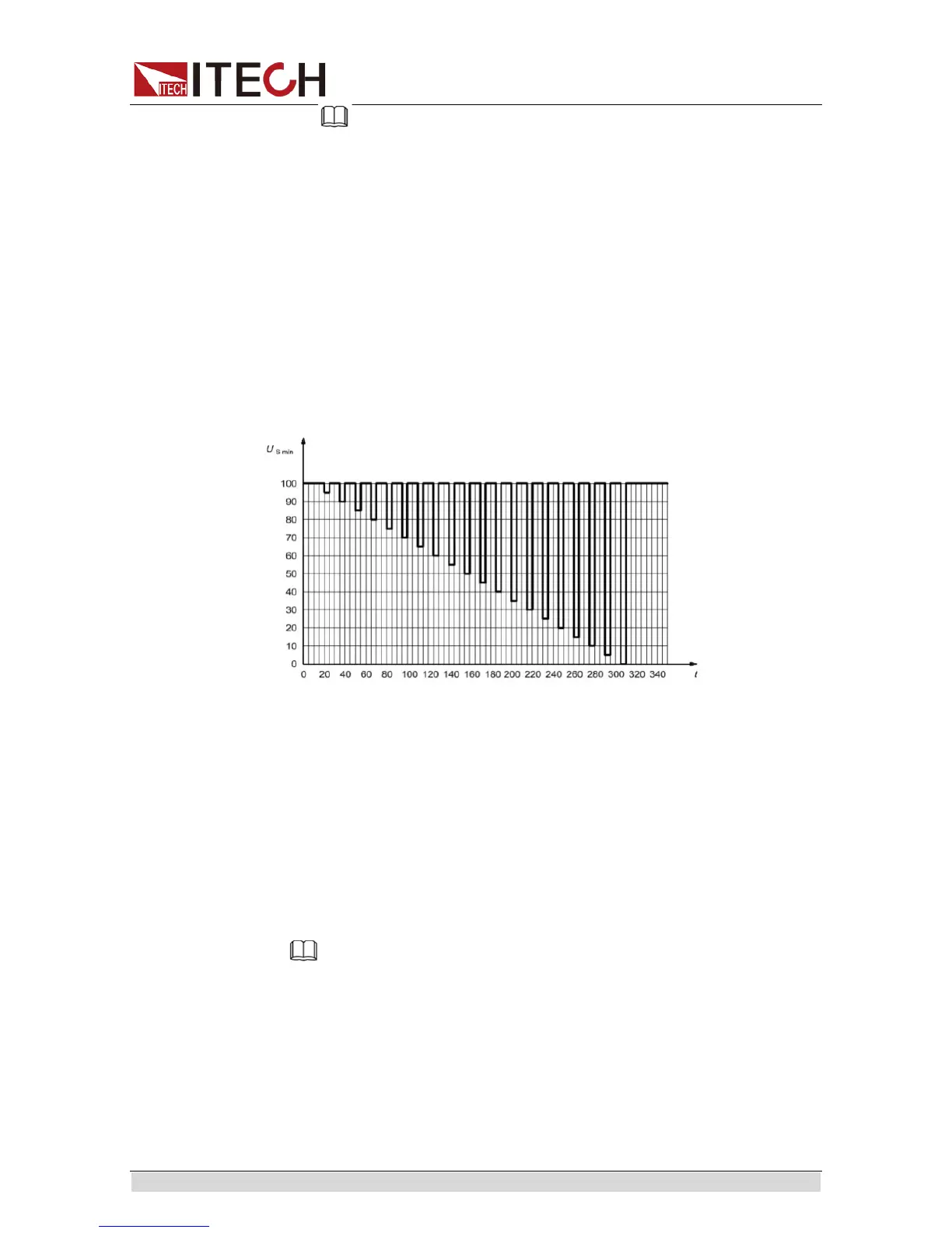
Reset Test
This test verifies the reset behavior of the DUT at different voltage drops. This
test is applicable to equipment with reset function, e.g. equipment containing
microcontroller.
Apply the test pulse simultaneously in figure below to all relevant inputs
(connections) and check the reset behavior of the DUT. Decrease the supply
voltage by 5 % from the minimum supply voltage, USmin, to 0,95USmin. Hold
this voltage for 5 s. Raise the voltage to USmin. Hold USmin for at least 10 s
and perform a functional test. Then decrease the voltage to 0,9USmin.
Continue with steps of 5 % of USmin, as shown in Figure 6, until the lower value
has reached 0 V. Then raise the voltage to USmin again.
How to recall “Profile for the reset test” waveform from menu (take 12V system
as an example):
1. Press [Shift]+ [I-set] (Function) to enter the menu operation.
2. Press Right direction key to select ISO16750-2, press [Enter]
3. Press Up/Down direction keys to select “Reset”, press [Enter].
4. VFD display Usmin…, press [Enter] to confirm. VFD will display
Usmin=12.000V, user can select the Usmin level.
5. Press Right direction key to “On”, press [Enter].
6. VFD will display ISO-Reset in the lower right corner.
7. Press [On/Off], turn on the output.
8. Press [Shift]+[Enter] (Trigger) to generate a trigger signal. The DC source
will output Short voltage drop waveform. The Trig indicating lamp will be lit
and display on the VFD.
Note
Please make sure the trigger source is selected in MANUAL item in above
operations(refer to step 8th). And user need to turn on the internal load to speed
up the falling time during ISO16750-2 waveform operations.
Starting Waveform
This test verifies the behavior of a DUT during and after cranking.
Apply the starting profile ten times, as specified in Figure and Table below
simultaneously to all relevant inputs (connections) of the DUT. A break of 1 s to
2 s between the starting cycles is recommended. One or more profiles as
described in Tables 3 and 4 shall be chosen in accordance with the application.