EasyManua.ls Logo

ITech IT8512C+ User Manual

ITech IT8512C+
80 pages
To Next Page IconTo Next Page
To Previous Page IconTo Previous Page
Page #32 background image
Functions and Characteristics
Copyright © Itech Electronic Co., Ltd. 23
setup page.
HIGH=120.0V
CR
Note
In CR mode, the user can also set the minimum value of the voltage.
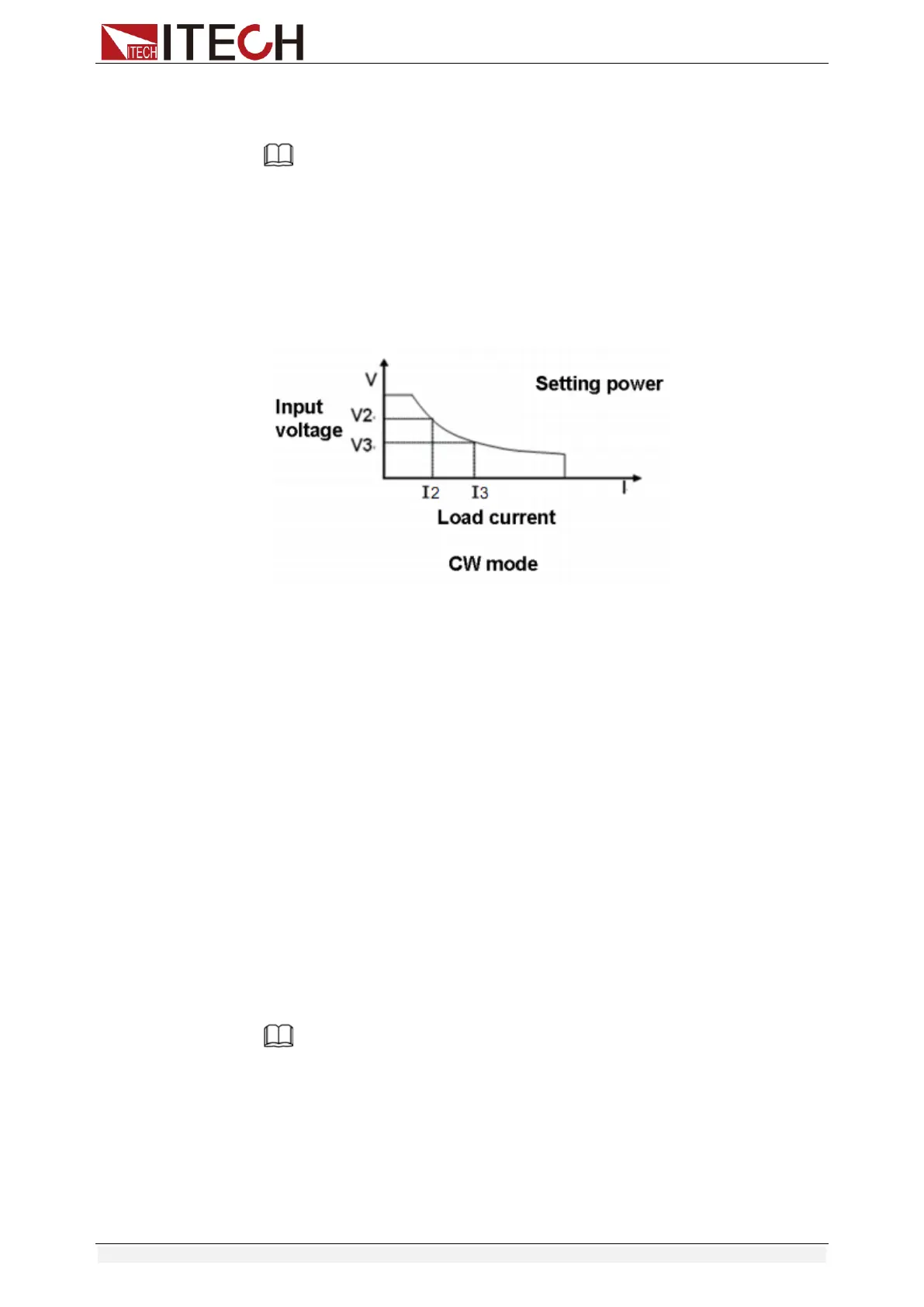
3.2.4 Constant Power Mode (CW)
In constant power mode, the electronic load will consume a constant power, as
shown in the figure below, if the input voltage rises, the input current will
decrease and the power P (= V * I) will remain at the setting value.
Diagram 3-4 I-V curve in CW mode
There are two ways to set the power value:
In CW mode, rotate Rotary knob.
In CW mode, input value through number keys directly, press [Enter] to
confirm.
Steps
1. Press [CW], and then press [Shift]+[CV](Setup) to enter into the
parameters setting page.
RANGE=150.00W
CW
2. Set the maximum working resistance value, and press [Enter] to confirm.
RANGE =100.00W
CW
3. Set the maximum working voltage value, and then press [Esc] to exit the
setup page.
HIGH=120.00V
CW
Note
In CW mode, the user can also set the minimum value of the voltage.
3.3 Input On/Off Control
[On/Off] button on the front panel is used to manually control input on or off.
[On/Off] button lighted indicates the load input is turned on, and the
real-time voltage and current information about the current loop is
displayed on the VFD screen.

Table of Contents

Other manuals for ITech IT8512C+

Question and Answer IconNeed help?

Do you have a question about the ITech IT8512C+ and is the answer not in the manual?

ITech IT8512C+ Specifications

General IconGeneral
BrandITech
ModelIT8512C+
CategoryTest Equipment
LanguageEnglish

Summary

Chapter 1 Inspection and Installation

1.6 Connect the Power Cord

Precautions and steps for safely connecting the power cord to the instrument.

1.7 Connect the Device Under Test (DUT)

Steps and safety precautions for connecting the device under test to the load.

Chapter2 Quick Start

2.3 Front Panel Introduction

Description of front panel controls, display, and their respective functions.

2.4 Front Panel Keys

Explanation of individual front panel keys and their combined usage for operations.

Chapter 3 Functions and Characteristics

3.2 Operation Mode

Explanation of the four primary operating modes: Constant Current, Voltage, Resistance, Power.

3.7 Config Menu (Config)

Configuration options for protection limits, timers, voltage range, and filters.

3.10 Test Function

Performing various tests including transient, OCP, OPP, and battery discharge.

3.13 Protection Function

Details on Over Voltage, Over Current, Over Power, and Over Temperature protections.

Chapter4 Automatic Test Function

4.2.1 Test Mode for IT8500+

Step-by-step guide for editing and saving test sequences in IT8500+ mode.

Chapter5 Specifications

Specifications

Detailed technical specifications for the IT8500+ series electronic loads.

Chapter6 Communication Interfaces

6.2 Communication with PC

Configuration steps for establishing communication with a PC via serial or USB interface.

Related product manuals