ITOH DENKI CO.,LTD.
(1 )
(2 )
(2 )
(2 )~(3 )
(3 )
(3 )~(4 )
(4 )
(4 )~(6 )
(4 )~(6 )
(7 )
(7 )
(7 )
(8 )
(8 )~(9 )
(9 )
(10)~(11)
(12)
(13)
(13)
(13)
1 Safety Instructions
2 Power
3 Before Operating the Product
3-1 Mounting
3-2 Wiring
3-3 Direction Setting
4 Functions
5 Operation Instructions
5-1 Speed Variation
5-1-1 Internal Speed Variation
5-1-2 External Speed Variation
5-2 Direction Setting
5-3 Acceleration and Deceleration
6 Error Signal Output
7 Motor Pulse Signal Output
8 Error status, Reset, History
8-1 Error History
8-2 Indication of Error Occurrence Frequency
9 Troubleshooting
10 Dimensions
11 Product specifications
12Applicable standards
( -UL)
Standard Accessories
INDEX
● Power connector (CN 1)
● Control connector (CN 2)
● Mounting screws and nuts
Screw M4 x 15
Nut M4
1pce
1pce
2pcs
2pcs
Power connector
(CN 1)
Control connector
(CN 2)
No.491
PM486FE・PM500FE
PM486FS・PM500FP
PM486FP
PM570FE・PM605FE・PMT42FE
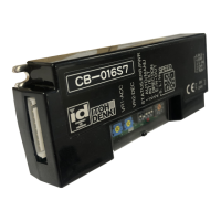
CB-016S7/LT-UL
Applicable MDR models Motor driver model
S : For standard motor,
NPN signal input and output
P : For standard motor,
PNP signal input and output
BS : For built-in brake motor,
NPN signal input and output
BP : For built-in brake motor,
PNP signal input and output
LT : Low Temp
UL : UL recognized
(1)
Maximum Surrounding Air Temperature40℃.
Switch off the power, when removing from conveyor, wiring or maintenance is
done, otherwise you have a risk of electrical shock or injury.
Respect the electrical regulations of the site or the equipment, where the
product in installed. (Labor safety and sanitary regulations, electrical
equipment technical standard, etc)
Operate the motor driver within its intended design and specifications to
avoid electrical shock, injury, fire, or damage to the equipment.
Do not disassemble, repair nor modify the product (for which we do not
warrant) It might cause electrical shock, injury or fire.
Separately set the circuitry to monitor the important input and/or output signal
status, which might cause accident, because the signal may stay ON or OFF
in case of the CB-016 driver card failure.
Be sure to shut off the power before inserting or removing any connector. Do
not wire connector left in the CB-016 driver card.
Do not drop, give external impact nor pressure to the CB-016 driver card. If
that happens, do not reuse it.
Make sure all the connectors are properly engaged with wiring cables.
Make sure the conveyor frame and control box where the CB-016 driver card
is mounted are grounded.
Do not switch on or off the relay or contactor in close proximity to power or
signal lines, or the CB-016 driver card as the generated noise could cause
malfunction.
Be sure to inject power or input signal for 15 milli-seconds or over to ensure
the proper reaction.
Use the MDR with built-in brake option (BR) along with CB-016 driver card
〔BS7〕〔BP7〕 if holding effect is needed.
Do not pull by force during operation. It causes the CB-016 driver card to
malfanction.
Do not force the MDR to turn. It may cause of damage to the driver card or
shorten its life cycle.
1 Safety Instructions
●
●
●
●
●
●
●
●
●
●
●
●
●
●
●
Connenctor may harden with low temperature.
Do not insert or pull it by force.
Mount this product to the place where MDR can be properly connected
without cable loose, extreme bend or pull, or move.
MDR speed may not reach immediately to the set speed if it is left long hours
in 0℃ or below. In addition, the starting current may get larger to activate
thermister, or under voltage error may be resulted. Therefore , warm up
operation is recommended before formal use.
Be careful for condensation or freeze in case the product is used in varying
temperature particularly between below and above 0℃. If condensation is
generated, do not use the product until it is completely removed. Use of the
product having condensation may result in malfunction or electrical accident.
●
●
●
●
<Described below are the precautions for using this product at freezing
temperature along with MDR having LT option:>
Warning & Caution
Possible danger of light or medium injury, or only a
material damage.
Warning
Incorrect handling may lead to death or serious injury,
indicating potential danger.
Shown below are the caution items for using the product safely and avoiding
danger and damage to the user.
Caution items can be classified into danger, warning and caution as described
below.
Caution
Caution
Brushless DC Motor Driver
【CB-016〔S7〕〔BS7〕〔P7〕〔BP7〕】User Manual
Thank you for purchasing a Itoh Denki CB-016 series
motor driver. Please read this manual before operating
the product, and keep this manual readily accessible for
reference.