7
Power Units (All Potted Models)
5200095 Rev C
Removal of Shielded Cable from Power Unit
1. Disconnect line voltage to power unit.
2. Remove hex nut (item 3) and cable clamp (item 1).
3. Loosen spring-loaded high voltage connector (item 11) and remove from high voltage
output terminal of power unit.
4. Remove set-screw (item 12) from the spring-loaded high voltage connector with a
5/64” Allen wrench to remove connector from shielded cable.
5. Loosen and remove both sections of the nylon compression fitting (items 9a, 9b). The
protective sleeve (item 10) should remain on the cable.
6. Remove hex nut (item 8). The entire cable assembly may now be removed from the
power unit.
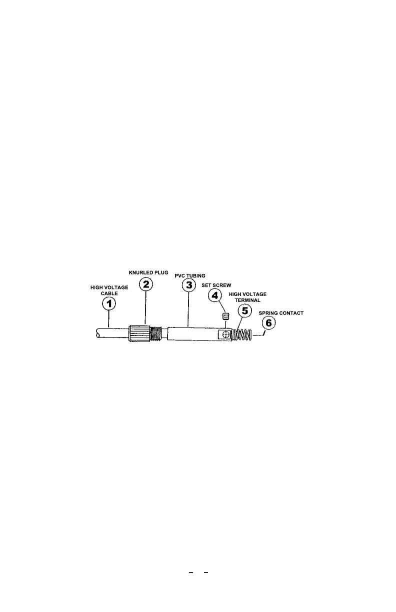
Installation of Spring-Loaded High Voltage Connector
Two types of high voltage cables are used on Simco-Ion equipment. The larger diameter
cable (black) requires the 5050001 connector and the smaller diameter cable (red) uses the
5050002 connector. Installation of both connectors is the same with the exception of step
“1 “. Refer to Figure 2 below for details.
1. For black cable, measure and strip 1/2” insulation from end of cable. Straighten
conductor strands.
2. For red cable, measure and strip 1” insulation from end of cable. Straighten conductor
strands and bend back to form a double thickness 1/2” long.
3. Slide the knurled plug (item 2) onto the cable (item 1) with the threaded end toward
the end of the cable.
4. Slide the PVC tubing (item 3) over the cable with the set screw hole positioned
toward the end of the cable.
5. Slide the high voltage terminal (item 5) over the conductor until it butts against
the cable insulation. Make certain all conductor strands are inside the high voltage
terminal.
6. Align set screw holes of the PVC tubing and high voltage terminal.
7. Insert and tighten set screw. Pull firmly on the cable to ensure the set screw is well
seated and tight.
8. Screw the spring contact (item 6) onto the high voltage terminal.