81
@
COOLING
SYSTEM
RAFFREDDAMENTO
8101
Industrial
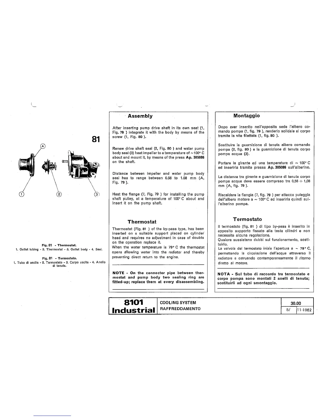
Fig.
81
-
Thermostat.
1.
Outlet tubing
-
2.
Thermostat
-
3.
Outlet
body
-
4.
Seal.
Fig.
81
-
Termostato.
I.
Tubo
di
uscita
-
2.
Termostato
-
3.
Corpo
uscita
-
4.
Anello
di
tenuta.
3a.00
5/
11-1982
Assem
bly
After inserting pump drive shaft In its own seat
(1,
Fig. 79
)
integrate
it
with the body by means of the
screw
(1,
Fig.
80
).
Renew drive shaft seal
(2,
Fig.
80
)
and water pump
body seal
(3)
heat impeller to a temperature of
-100"
C
about and rnount
it,
by means of the press Ap.
305086
on the shaft.
Dlstance between impeller and water pump body
seal has to range between
0.56
to
1.08
mm (A,
Fig. 79
).
Heat the flange
(7,
Fig. 79
)
for installing the pump
shaft puliey, at a temperature of
100°C
about and
insert
it
on the pump shaft.
T
hermostat
Thermostat (Fig.
81
)
of the by-pass type, has been
lnserted on a suitable support placed
on
cylinder
head and requires
no
adjustment in case of doubts
on the operation replace it.
When the water temperature
is
79"
C
the thermostat
opens dllowing water into the radiator and thereby
preventing direct return to the engine.
NOTE
-
On the connector pipe between ther-
mostat
and
pump body two sealing ring are
fitted-up; replace them at every dicassembling.
Montaggio
Dopo
aver inserito nell'apposita sede i'albero co-
mando pompa
(1,
fig. 79
),
renderlo solidale ai corpo
tramite la vite filettata
(1,
fig.
80
).
Sostituire ia guarnizione di tenuta albero comando
pompa
(2,
fig.
80)
e
la guarnizione di tenuta corpo
pompa acqua
(3).
Portare la girante ad una temperatura di
-
100"
C
ed inserirla tramite pressa
Ap.
305086
sull'aiberino.
La distanza tra girante
e
guarnizione di tenuta corpo
pompa acqua deve essere compreso tra
0,56
+
1,08
mm (A, fig. 79
).
Riscaldare la flangia
(7,
fig. 79
)
per attacco puleggia
dell'albero motore a
-
100"
C
ed inserirla quindi sui-
I'aiberino pompa.
Termostato
Il
termostato (fig.
81
)
di tipo by-pass
è
inserito in
apposito supporto fissato alla testa cilindri e non
necessita alcuna regolazione.
Qualora sussistano dubbi
sul
funzionamento, sosti-
tuirlo.
La valvola dei termostato inizia l'apertura
a
-
79'
C,
permettendo
la
circolazione dell'acqua attraverso
il
radiatore
e
ostruendo contemporaneamente
il
ritorno
diretto
al
motore.
NOTA
-
Sul
tubo
di
raccordo tra termostato
e
corpo pompa
sono
montati
2
anelli
di
tenuta;
sostituirli ad
ogni
smontaggio.
 Loading...