Do you have a question about the Iveco N45 MNA M10 and is the answer not in the manual?
Details on engine model, serial number, and related identification markings.
Safety instructions, handling guidelines, and installation precautions for engine operation.
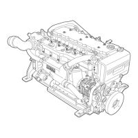
Illustrated overview of key engine components and their labels for identification.
Specifications for air flow, temperatures, pressures, and inclination angles for engine installation.
Guidelines for engine accessibility, anchoring, ventilation, cooling, and electrical connections.
Requirements and materials for installing the engine's fuel supply system.
Visual representation of components and operations for installing the M10.00/M15.00 engine.
Details on engine electrical components, wiring harnesses, and connections for M10.00/M15.00.
Description and connection details for the main analog instrument panel.
Installation and operation of the secondary analog instrument panel for flying bridge controls.
Dimensions and layouts for drilling mounting holes for analog instrument panels.
Information on wiring and connecting customized instrument panels and their modules.
Comprehensive wiring diagrams for the M10.00/M15.00 engine electrical systems.
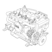
Visual representation of components and operations for installing the M10.01/M15.01 engine.
Details on engine electrical components, wiring harnesses, and connections for M10.01/M15.01.
Description and connection details for the main analog instrument panel for M10.01/M15.01.
Installation and operation of the secondary analog instrument panel for flying bridge controls.
Dimensions and layouts for drilling mounting holes for analog instrument panels.
Information on wiring and connecting customized instrument panels and their modules.
Comprehensive wiring diagrams for the M10.01/M15.01 engine electrical systems.
Technical details and specifications for various engine sensors and their signals.
Step-by-step procedure for preparing the engine before its initial start.
Pre-start checks for the engine and instrument panel operation.
Procedure and checks for the initial starting of the engine.
Procedures for monitoring engine performance and conditions during operation.
Procedures for storing the engine for extended periods of inactivity.
Supplementary information, including details on remote oil filters.