EasyManua.ls Logo

Iveco NEF N60-ENT-M40 User Manual

Iveco NEF N60-ENT-M40
70 pages
To Next Page IconTo Next Page
Page #1 background imageLoading...
Page #1 background image
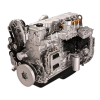
NEF
N40 ENT M25
N60 ENT M37 - M40
4 - 6 CYLINDERS IN LINE
DIESEL CYCLE
FOR MARINE APPLICATIONS
INSTALLATION DIRECTIVE
MAY 2006 EDITION
T E C H N O L O G I C A L E X C E L L E N C E
Question and Answer IconNeed help?

Do you have a question about the Iveco NEF N60-ENT-M40 and is the answer not in the manual?

Iveco NEF N60-ENT-M40 Specifications

General IconGeneral
BrandIveco
ModelNEF N60-ENT-M40
CategoryEngine
LanguageEnglish

Summary

NEF Installation Directive

1. WARNINGS AND CAUTIONS

Safety, Handling, and Installation Procedures

Safety precautions, handling, installation, and electrical safety guidelines.

Start-up and System Testing

Procedures for initial engine start-up and system tests.

4. GENERAL INSTALLATION CRITERIA

7. FUEL LINE

8. ELECTRICAL EQUIPMENT

Power Supply Line and Batteries

Engine Ground and Battery Recharging

Engine Electrical Ground Connection

Procedure for connecting the engine electrical ground.

Battery Recharging Process

How the battery is recharged via the alternator.

Central Electronic Unit (ECU) and Relay Box

ECU Connections and Relay Box Functionality

Details of ECU connectors and relay box installation/function.

Sensor Installation and Testing

Throttle Lever and Water Sensors

Testing throttle sensor and installing water presence sensor.

9. MAIN ANALOG INSTRUMENT PANEL

Panel Installation, Operation, and Testing

Connecting, operating, and testing the main analog instrument panel.

10. SECONDARY ANALOG INSTRUMENT PANEL

12. MAIN DIGITAL INSTRUMENT PANEL

CAN - BUS Converter Module

Panel Operation and Programming

Programming Accessory Functions

Steps for programming maintenance intervals and fuel consumption.

13. SECONDARY DIGITAL INSTRUMENT PANEL

15. CUSTOMIZED INSTRUMENT PANEL

16. SENSORS FOR DETECTION AND PANEL SIGNALING

Sensor to Detect Water in Fuel

17. PREPARING ENGINE FOR FIRST START-UP

18. TESTS BEFORE FIRST START-UP

19. FIRST ENGINE START

Engine Start-up Procedures and RPM Control

Steps for starting the engine and controlling RPM.
20. EDC ANOMALIES INDICATION

21. BLINK CODE TABLE

22. UNDERWAY CHECKS

23. PREPARING ENGINE FOR LONG IDLE PERIODS

24. WIRING DIAGRAMS

EDC Connector A2 Wiring

EDC Connectors A - A1

Main Analog Instrument Panel

Secondary Analog Instrument Panel

CAN-BUS Converter Module Interface Wiring

Wiring of a Specific Personalised Instrument Board

Wiring of Double Personalised Instrument Board

Electronic Control Governing Levers

Interface Wiring and JD Connector

Related product manuals