Do you have a question about the Iveco NEF N40-ENT-M25 and is the answer not in the manual?
Safety precautions for personnel, handling, and installation.
Warnings and procedures for engine start-up and testing.
Procedures for preparing the engine for long periods of inactivity.
Criteria for accessibility, anchoring, ventilation, and air.
Guidelines for sea water lines and exhaust gas discharge.
Recommendations for pre-heating and electrical equipment arrangement.
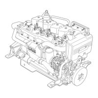
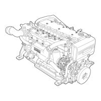
Specifications for optional power takeoffs and engine dimensions.
Overview of fuel line, pre-filter, material characteristics, and connections.
Overview of electrical equipment and component codes.
Installation, operation, and testing of the main analog panel.
Procedure for calibrating the revolution counter.
Installing, operating, and testing the secondary analog panel.
Installing and connecting the main digital instrument panel.
Installing, operating, and testing the secondary digital panel.
Details on the JD connector for indications and alarms module.
Specifications for coolant, oil pressure, and exhaust gas sensors.
Specifications for air filter clogging and water in fuel sensors.
Tests for fuel suction, throttle sensor, and instrument panel.
Steps for first engine start and RPM control.
Understanding EDC anomalies, blink codes, and error deletion.
Checks for ECU, compartment, air, exhaust, fuel, and pressure.
Reference list for electrical components and their codes.
Detailed wiring diagram for EDC connector A2.
Detailed wiring diagrams for EDC connectors A and A1.
Wiring diagram for the main analog instrument panel.
Wiring diagram for the secondary analog instrument panel.
Interface wiring for the CAN-BUS converter module.
Wiring diagram for supplementary services battery recharge.
Wiring for a specific personalised instrument board.
Wiring for a double personalised instrument board.
Information on electronic control governing levers.
Details on remote oil filter installation and specifications.
| Engine Model | NEF N40-ENT-M25 |
|---|---|
| Category | Engine |
| Engine Type | 4-stroke diesel |
| Displacement | 3.9 liters |
| Bore x Stroke | 104 mm x 115 mm |
| Compression Ratio | 17.5:1 |
| Aspiration | Turbocharged |
| Fuel Type | Diesel |
| Emission Standards | Tier 2 |
| Cooling System | Liquid-cooled |
| Fuel System | Common rail direct injection |