C78 ENT M50 INSTALLATION INSTRUCTIONS
9
FEBRUARY 2003 EDITION
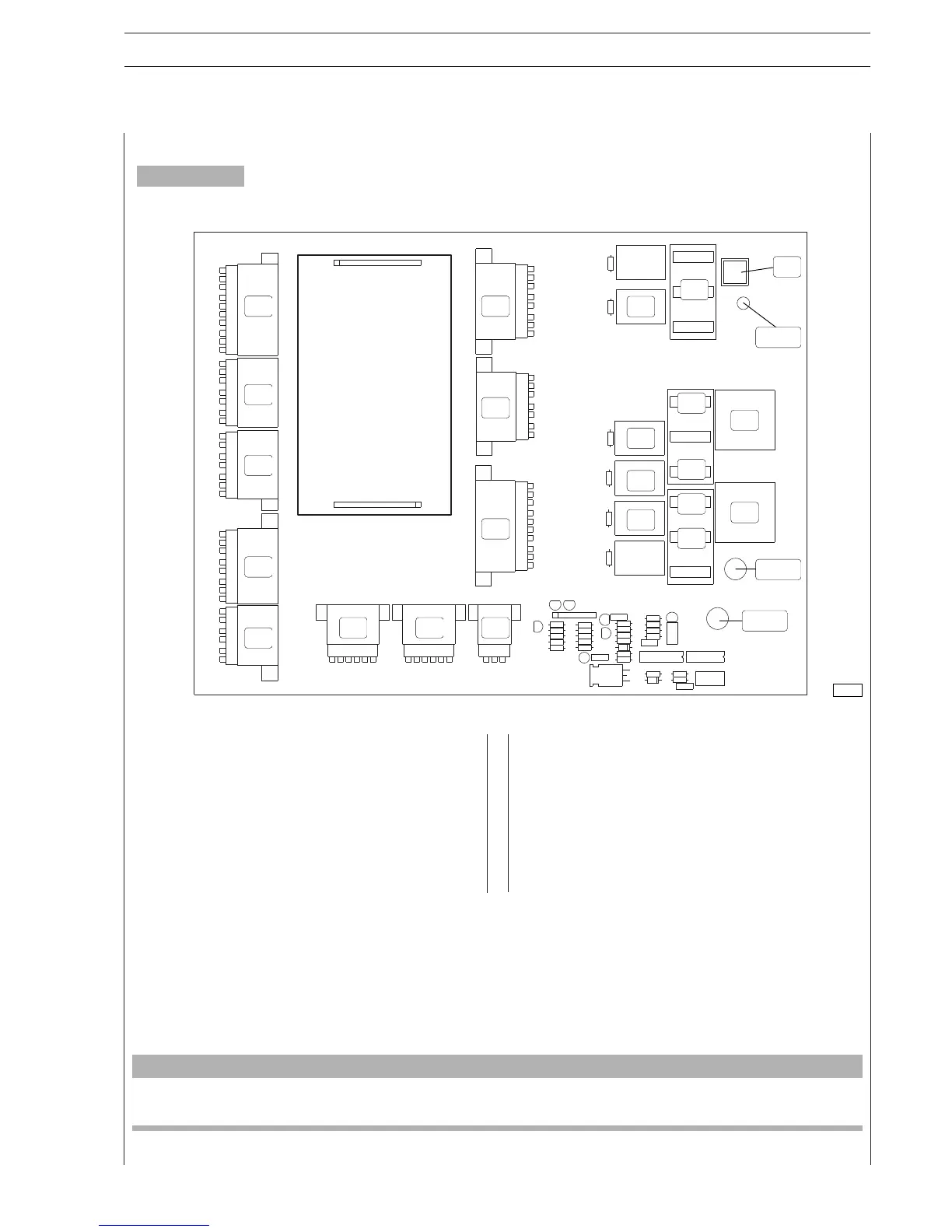
Fuses
F1 EDC power supply
F2 alternator recharge indication circuit
F3 not used
F4 not used
F5 intercooler bypass
F6 not used
F7 master power supply
F8 electrical oil pump
F9 not used
Relays
K1 EDC main
K2 not used
K3 not used
K4 not used
K5 intercooler bypass control
K6 key switch discharge
K7 engine shut down
K8 starter control
K9 pre-lubricating oil pump control
E
D
C
M
Z
Y
K9
K7
K6
K5
K8
K1
F7
F5
F2
F1
F8
T
F
VKP
S2
LD1
CNB1
Figure 5
CNA1
E – D- C- M- Z- P- K- V- F- T –Y = wire / board electrical wiring connectors
CNAI = connection to battery’s positive pole
CNBI = connection to terminal 50 of the electrical starter engine
PI = push-button for emission of EDC error codes
LDI = indicator light signaling the emission of EDC error codes
Location of components on relay and fuse board
81423
CAUTION
If magneto-thermal protection and intervention devices are interposed, they must not be used to shut the engine down or
otherwise used just a few seconds after shutting the engine down.
 Loading...
