C78 ENT M50INSTALLATION INSTRUCTIONS
8
FEBRUARY 2003 EDITION
ELECTRICAL CIRCUIT
Electrically insulate the container, if secured to a metal bulk-
head, to avoid the onset of parasite currents, and connect it
to the negative terminal of the battery. The position must
allow for easy access to the fuses and the diagnosing push-
buttons contained in it, even when underway. No modifica-
tion is allowed to the wiring.
EMB (Electronic Management Box)
This is the housing for the electrical and electronic units
managing and controlling the engine’s operation. It is sup-
plied fastened to the engine in such a position as to allow
for an easy access to the electrical components. If it is nec-
essary to position it differently, fasten it in the vertical posi-
tion with the wire bundles to the engine projecting down-
wards and at such a distance that no modifications to the
engine wiring are required.
GENERAL NOTES
DO NOT USE wiring belonging to the engine’s electrical equipment to supply power to other devices in the boat.
PLACE engine electrical wiring independently from the other wiring installed on the boat.
USE of switches or battery disconnects on the EMB power supply line is not allowed.
EXTREME CARE SHOULD BE PLACED in the polarization of the electrical connections and in the correct coupling of their
locking elements.
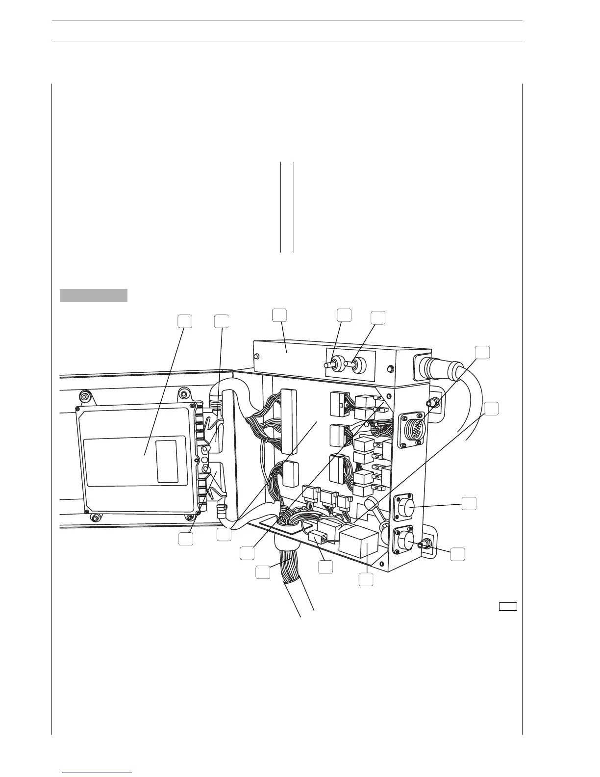
1. EDC system electronic control unit - 2. ECU B connector - 3. Pre-lubrication control unit - 4. Electrical pre-lubrication
pump intake/exhaust enabling control - 5. Pre-lubrication/engine oil replacement solenoid valve enabling control -
6. G connector for instrument panel wiring - 7. Fitting for negative polarity – electrical ground connections - 8. Q connector
for diagnostic instrument connection - 9. H connector for power supply grid wiring - 10. Grid heater relay - 11. Alternator
excitation resistor - 12. Engine electrical wiring and throttle potentiometer - 13. Location of blink-code push-button and
indicator light - 14. Relay and fuse box - 15. ECU A connector.
Figure 4
1 2
3 4
5
6
7
8
9
10
11
12
13
14
15
81422
 Loading...
