Figure 65
Figure 66
Figure 67
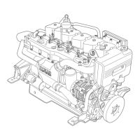
Use apparatus 99395363 (1) to check parallelism of the rod
arms. T he maximum permitted tollerance is ± 0.05 mm,
measured at 125 mm from the longitudinal axis of the rod. If
a misalignment exceeding the permitted tolerance is encoun-
tered, replace the rod.
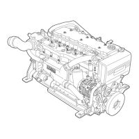
- Position the pi ston (1) on the rod (3), insert the pin (4)
and secure it with the piston rings (2).
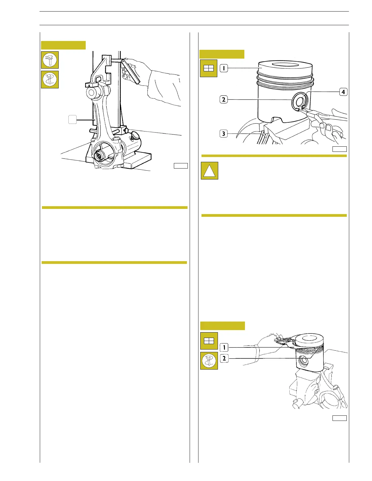
- Insert the piston rings (2) on the piston using pliers
99360183 (1).
The body and cap of every connecting rod is marked
with a number indicating the part with which is to be
mated. In addition, the number of the cylinder where
the rod should be installed may be stamped on it.
Therefore, when replacing the rod, it is necessary to
mark the new rod with the same number as the rod
whitch is being replaced.
!
Fitting the piston rings
1
Check of connecting rod alignment Fitting the connecting rod—piston assembly
Connecting rod—piston mating
The connecting rod — piston coupling must be made
taking account that, on fitting the assembly in the cylin-
der block, the wording ”TAPPET SIDE” (stamped on
the crown of the piston) must be fac ing the tappet
side of the engine and the numbering of the connect-
ing rods must be facing the corresponding numbering
stamped on the cylinder block.
16557
37715
16817
NOTE
SECTION 4 - OVERHAUL AND TECHNICAL SPECIFICATIONS 31
VECTOR 8 ENGINES
Print P2D32V001E Base - April 2006