11
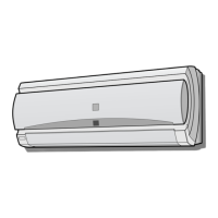
FRONT PANEL - REMOVAL AND ATTACHMENT
When servicing, for example, use the following procedure to detach/attach the front panel.
Disconnect the power or shut off the breaker before implementation.
Removal
(1) Remove the open panel.
1. Push the release button and open the lower part of the
open panel.
2. Lift the open panel up slightly and remove it.
(2) Open the lter cover
(3) Remove the wire cover with a slotted screwdriver.
(4) Remove the nine connectors.
(5) Remove the front panel.
1. Unscrew the four screws on the front panel.
2. Release the three hooks along the upper surface.
Attachment
(1) Replace the front panel
1. Insert the three hooks along the upper surface into the unit.
2. Push the bottom of the front panel to the unit.
3. Tighten the four screws on the front panel.
(2) Connect the nine connectors.
(3) Replace the wire cover.
(4) Close the lter cover.
(5) Replace the open panel.
1. Hook both tabs on the shaft.
2. Close the open panel.
12
Screw
Filter cover
Open panel
Front panel
Release button
Wire cover
Filter cover
Screw
Wire cover
1
2
Tab
Shaft
PUMP DOWN
(Pump down is adopted in the case of unit removal for re-installation, abandonment, repair etc.)
(5) After 2~3 minutes, immediately close the 3-way valve fully.
(6) Stop the test run operation.
(7) Replace both valve shaft caps tightly.
(8) Disconnect both refrigerant pipes.
Caution:
Make sure that the compressor is turned off before removing the
refrigerant pipes. Otherwise, it will cause burst and injury
Pump down is to collect the refrigerant into the outdoor unit by
control of the 2 and 3-way valves and the compressor.
(1) Stop the air conditioner operation.
(2) Remove both valve shaft caps of the 2 and 3-way valves.
(3) Run the air conditioner at cooling test run mode (Refer to 11
TEST RUN). If pump down is performed at normal cooling
operation, the protection system may engage and stop the
operation.
(4) After 5~10 minutes, fully close the 2-way valve by turning
the hexagon socket screw key clockwise.
9
10
Remote control
rear side
6 SPECIAL SCREW
2 WALL PLUG
5 DRY BATTERY
Prepare a dedicated power supply circuit.
Supply power 220 V - 240 V, single-phase
Circuit breaker 10 A
(1) Start the operation with the
remote control.
(2) To start test run in cooling, hold
down the AUX button on the unit
for over 5 seconds until a beep
sound is heard and an operation
lamp ashes.
(3) To put the system in the heating
test run
mode, select heat mode
on the remote control while the
unit is in cooling test run mode.
(4) Make sure the system runs well.
To stop the operation, press the
AUX button again.
Is the specied power supply voltage used?
Is the connecting cable xed to terminal board rmly?
Is the earth wire connected properly arranged?
Is the drainage properly?
Is the indoor unit hooked to the mounting plate rmly?
Is there any gas leakage at the pipe connection?
• Fit a disconnect switch, having a contact separation of
at least 3mm in all poles, to the electricity power line.
(1) Fit the special
screw to the wall
with the wall plug.
(2) Hang the remote
control to the
screw head.
Explanation to customer
• Explain to the customer how to use and maintain the system,
referring to the operation manual.
• Ask the customer to carefully read the operation manual.
• When the system has been set up, hand the installation manu-
al to the customer.
POWER CABLING
HANGING THE REMOTE CONTROL
TEST RUN
ITEMS TO CHECK
12PHR-N_S530612PHRN.indd 6 2013/8/7 15:42:36
 Loading...