AEX12GRN
3 – 6
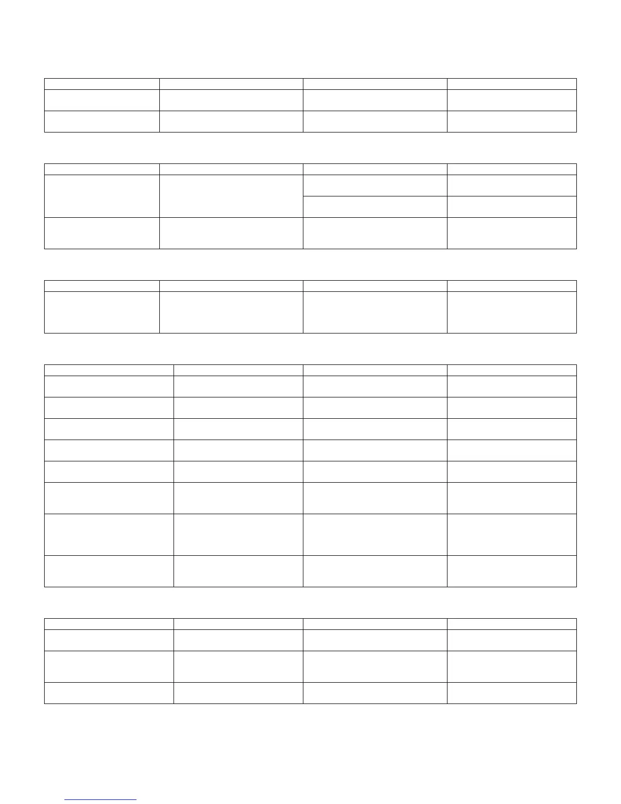
[5] GENERAL TROUBLESHOOTING CHART
1. Indoor unit does not turn on
2. Indoor unit fan does not operate
3. Indoor unit fan speed does not change
4. Remote control signal is not received
5. Louvers do not move
Main cause Inspection method Normal value/condition Remedy
Cracked PWB.
(Cracked pattern)
Check visually. There should be no cracking in PWB
or pattern.
Replace PWB.
Open-circuit in FU1 (250 V, 3
A), FU2 (250 V, 3 A)
Check melting of FU1, FU2. There should be no open-circuit. Replace PWB.
Main cause Inspection method Normal value/condition Remedy
Open-circuit in heat
exchanger thermistor (TH2)
(in heating operation)
Measure thermistor resistance (dis-
mount for check).
Refer to THERMISTOR TEMPERA-
TURE CHARACTERISTICS – 1
Replace thermistor.
There should be no open-circuit or
faulty contact.
Replace thermistor.
Disconnected heat exchanger
thermistor (TH2) (in heating
operation)
Inspect connector on PWB.
Check thermistor installation condi-
tion.
Thermistor should not be discon-
nected.
Install correctly.
Main cause Inspection method Normal value/condition Remedy
Remote control not designed
to allow fan speed change.
Check operation mode. Fan speed should change except dur-
ing dehumidifying operation, ventila-
tion, light dehumidifying operation,
internally normal operation
Explain to user.
Main cause Inspection method Normal value/condition Remedy
Batteries at end of service life. Measure battery voltage. 2.5 V or higher (two batteries in series
connection)
Install new batteries.
Batteries installed incorrectly. Check battery direction. As indicated on battery compartment. Install batteries in indicated direc-
tion.
Lighting fixture is too close, or flu-
orescent lamp is burning out.
Turn off light and check. Signal should be received when light
is turned off.
Change light position or install
new fluorescent lamp.
Use Sevick light (Hitachi). Check if Sevick light (Hitachi) is
used.
Signal may not be received some-
times due to effect of Sevick light.
Replace light or change position.
Operating position/angle is inap-
propriate.
Operate within range specified in
manual.
Signal should be received within
range specified in manual.
Explain appropriate handling to
user.
Open-circuit or short-circuit in wir-
ing of light receiving section.
Check if wires of light receiving
section are caught.
Wires of light receiving section should
not have any damage caused by
pinching.
Replace wires of light receiving
section.
Defective light receiving unit. Check signal receiving circuit
(measure voltage between termi-
nals 2 and 3 of connector
BCN3B).
Tester indicator should move when
signal is received.
Replace PWB.
Dew condensation on light receiv-
ing unit.
Check for water and rust. Signal should be received within
range specified in manual.
Take moisture-proof measure for
lead wire outlet of light receiving
section.
Main cause Inspection method Normal value/condition Remedy
Caught in sliding section. Operate to see if louvers are
caught in place.
Louvers should operate smoothly. Remove or correct catching sec-
tion.
Disconnected connector (DCNC,
DCND on relay PWB, louver
motor side)
Inspect connectors. Connectors or pins should not be dis-
connected.
Install correctly.
Contact of solder on PWB
(connector section on PWB)
Check visually. There should not be solder contact. Correct contacting section.
 Loading...