AEX12GRN
3 – 8
[6] MALFUNCTION (PARTS) CHECK METHOD
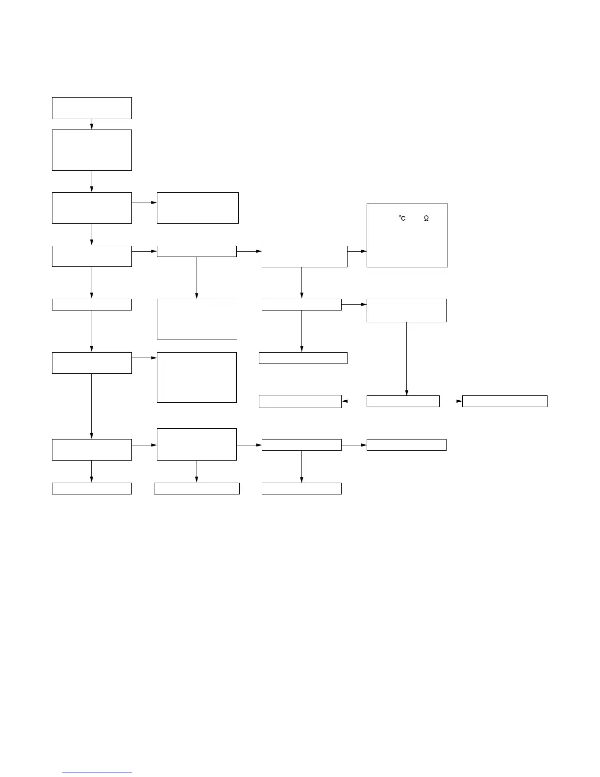
1. Procedure for determining defective outdoor unit IPM/compressor
The following flow chart shows a procedure for locating the cause of a malfunction when the compressor does not start up and a DC overcurrent indi-
cation error occurs.
YES
Immediately
after startup
YES
YES
NO
NO
NO
YES
NO
Connect power cord
to AC outlet.
Normal
NO
Replace outdoor unit PWB.
Using remote control,
operate air conditioner
so that compressor
starts.
Is there 230 VAC
between (1) and (N)
on outdoor unit PCB?
Is LED1 on outdoor
unit flashing?
Compressor starts up.
Does LED1 indicate
DC overcurrent error?
Does LED1 indicate
rotation error?
Outdoor unit PWB.
15/5 V display section.
Voltage OK.
Replace compressor.
Check inter-unit wiring.
Check indoor unit PWB.
Does LED1 remain lit?
Serial signal error.
Check inter-unit wiring.
Check indoor and
outdoor unit PWBs.
Replace outdoor unit
PWB.
Check compressor.
2/3-way valve closed.
Refrigerant shortage.
Replace outdoor unit
Is there 320 VDC between
pins IPM (31) and (35)?
+13 V, +15 V on PWB.
+13 V on PWB.
Replace outdoor unit PWB.
Replace expansion valve.
End.
Check posistor (PTC1)
(about 40 at 25 ).
Check IPM.
Check fan motor.
Check outdoor unit PCB.
Check wiring.
Check PAM IGBT (Q5).
Disconnect expansion
valve connector.
Replace outdoor unit PWB.
After about
20 seconds
YES
NO
NO
YES
NO
NO
YES
YES YES
No
(unlit)
OK
 Loading...