AEX12GRN
3 – 10
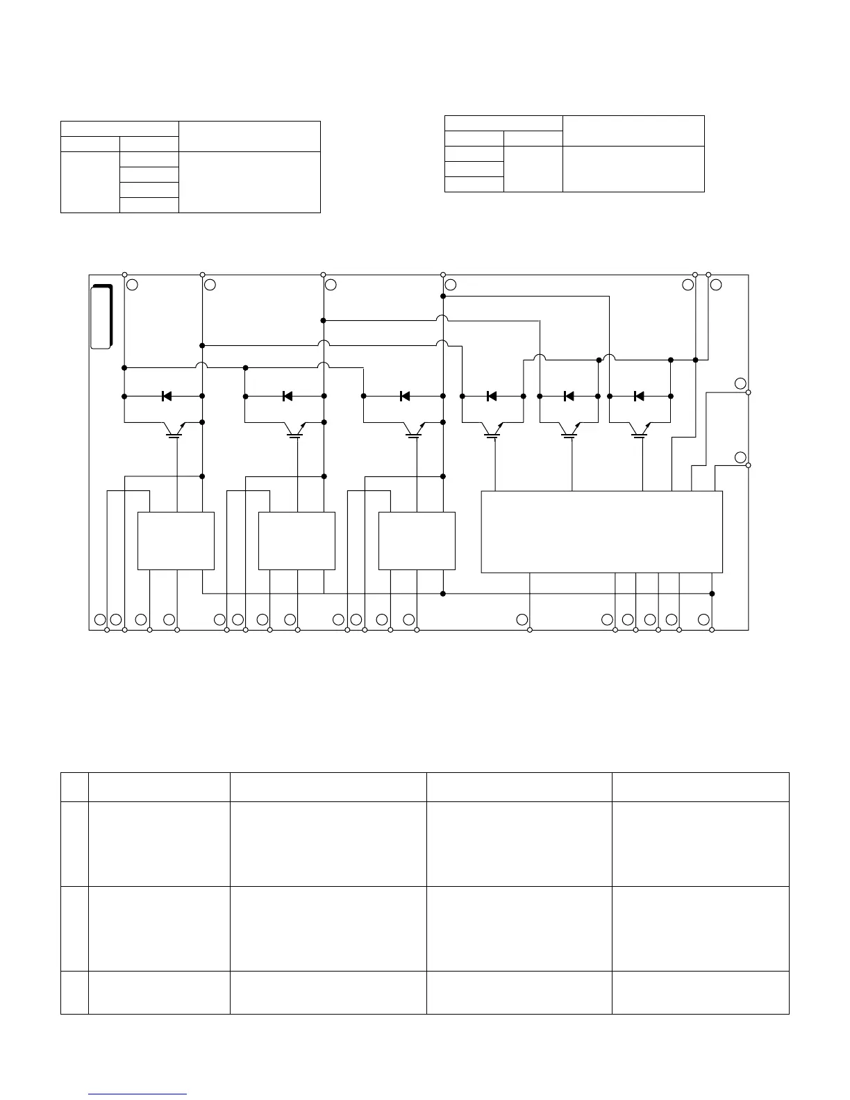
5. IPM check method
Turn off the power, let the large capacity electrolytic capacitor (C10) discharge completely, and dismount the IPM. Then, using a tester, check leak
current between C and E.
When using a digital tester, the (+) and (-) tester lead wires in the table must be reversed.
Values in ( ) are for digital tester.
5.1. IPM internal circuit diagram
[7] OUTDOOR UNIT CHECK METHOD
After repairing the outdoor unit, conduct the following inspection procedures to make sure that it has been repaired completely. Then, operate the
compressor for a final operation check.
1. Checking procedures
Needle-type tester Normal resistance value
(-) (+)
PN∞
(several MΩ)
U
V
W
Needle-type tester Normal resistance value
(-) (+)
UN∞
(several MΩ)
V
W
No
.
Item Check method Normal value/condition Remedy
1 Preparation Disconnect compressor cords (white,
orange, red: 3 wires) from compres-
sor terminals, and connect simulated
load (lamp used as load).
Operate air conditioner in cooling or
heating test operation mode.
2 Inverter DC power supply
voltage check
Measure DC voltage between IPM
pins (31) and (35).
320 VDC Replace control PWB.
Replace diode bridge.
Correct soldered section of Fas-
ten tabs (T1, T2, T5 - T3) on con-
trol PWB and IMP (S, C, R).
(Repair solder cracks.)
3 IPM circuit check Check that 3 lamps (load) light.
Check position detection voltage (+15
V, 5 V) on control PWB.
Each voltage should be normal.
All 3 lamps (load) should light with
same intensity.
Replace control PWB.
8
7($
8
$
*1
8
5
8
%%
*8+%
+0
%1/
8
$
*1
8
5
8
%%
*8+%
+0
%1/
8
$
*1
8
5
8
%%
*8+%
+0
%1/
7
176
8
176
9
176
8
01
0
%+0
%(1
%(1 %+0
8
%%
7
0
8
0
9
0
(Q
)0&
.8+%
8
7(5
8
2
7
2
8
8($
8
8(5
8
2
8
2
9($
9(5
8
2
9
2
8
0
8
7
0
8
0
9
0
(
1
8
0%
9
8
7
2
&+2+2/
 Loading...