Installation
AirModule –6 720 813 268(2014/10)
15
7.5 Water quality
Heat pumps operate with lower temperatures than other heating
systems, which means that the thermal degassing is not as effective and
the oxygen content will never be as low as in an electric/oil/gas system.
This means that the heating system will be more sensitive to rust with
aggressive water.
Do not use any water additives except for pH-enhancer and keep the
water clean.
Recommended pH level is 7.5 – 9.
7.6 Heating system flushing
The heat pump module is a part of a heating system. Problems in the heat
pump module can be caused by poor water quality in the radiators/floor
loops or by constant system oxygenation.
Oxygen causes corrosion products in the form of magnetite and
sediment.
Magnetite has a grinding effect on the heating system's pumps, valves
and components with turbulent flows such as the condenser.
Heating systems which require regular filling or where the heating water
does not produce clear water during water sampling require measures
prior to the installation of the heat pump, e.g. supplementing the heating
system with magnetite filters and air vent valves.
7.7 Operation without heat pump (stand-alone)
The heat pump module can be put into operation without a connected
heat pump, for example, if the heat pump is installed at a later date. This
is called "stand-alone" operation.
In stand-alone mode, the heat pump module uses only the integrated
immersion heater for heating and DHW production.
In connection with commissioning of stand-alone operation:
▶ Set Stand-alone mode in the service menu Heat pump ( Chapter
12.1).
7.8 Installation with cooling
Cooling is disabled in the UK model to comply with
the regulations for RHI.
▶ Insulate all connections and pipes from condensation.
▶ Install a room controller, with or without an integrated moisture
sensor ( manual for the respective room controller).
▶ Install condensation sensors ( Chapter 7.18).
▶ Select automatic mode heating/cooling ( Chapter 12.3.2,)
▶ Make the necessary cooling mode settings: start temperature, start
delay, room temperature and dew point differential (offset), as well
as lowest flow ( Chapter 12.3.2).
▶ Set the temperature differential (delta) over the heat pump (
Chapter 12.1.1)
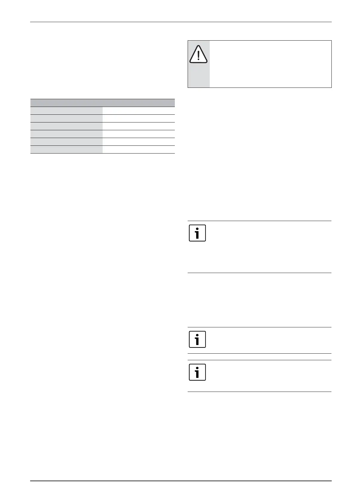
Water quality
Hardness < 3°dH
Oxygen content < 1 mg/L
Carbon dioxide, Co
2
< 1 mg/L
Chloride ions, Cl- < 250 mg/L
1)
1) Electric anode (accessory) in the water heater is recommended for higher
chloride content. If electric anode is used, it has to be purchased in
connection with commissioning.
Sulphate, So42- < 100 mg/L
Conductivity < 350 μs/cm
Table 10 Water quality
NOTICE: System damage due to objects in the pipes!
Objects in the pipes will decrease the flow and cause
operational problems.
▶ Flush out the system to remove all dirt residues
before connecting the heat pump and heat pump
module.
If the heat pump module and the heating system are
filled before the heat pump is connected, then the heat
transfer medium in and out to / from the heat pump must
be connected to secure circulation ( [1] and [2],
Fig. 13).
▶ Open shut-off valves on the heat transfer circuit, if
applicable.
Using cooling mode requires the installation of a room
controller (accessory).
Installation of a room controller with integrated humidity
sensor (accessory) makes cooling mode more secure as
the user interface automatically adjusts the flow
temperature in relation to the current dew point.