Electrical connections
6 720 643 409 (2010/03)
45
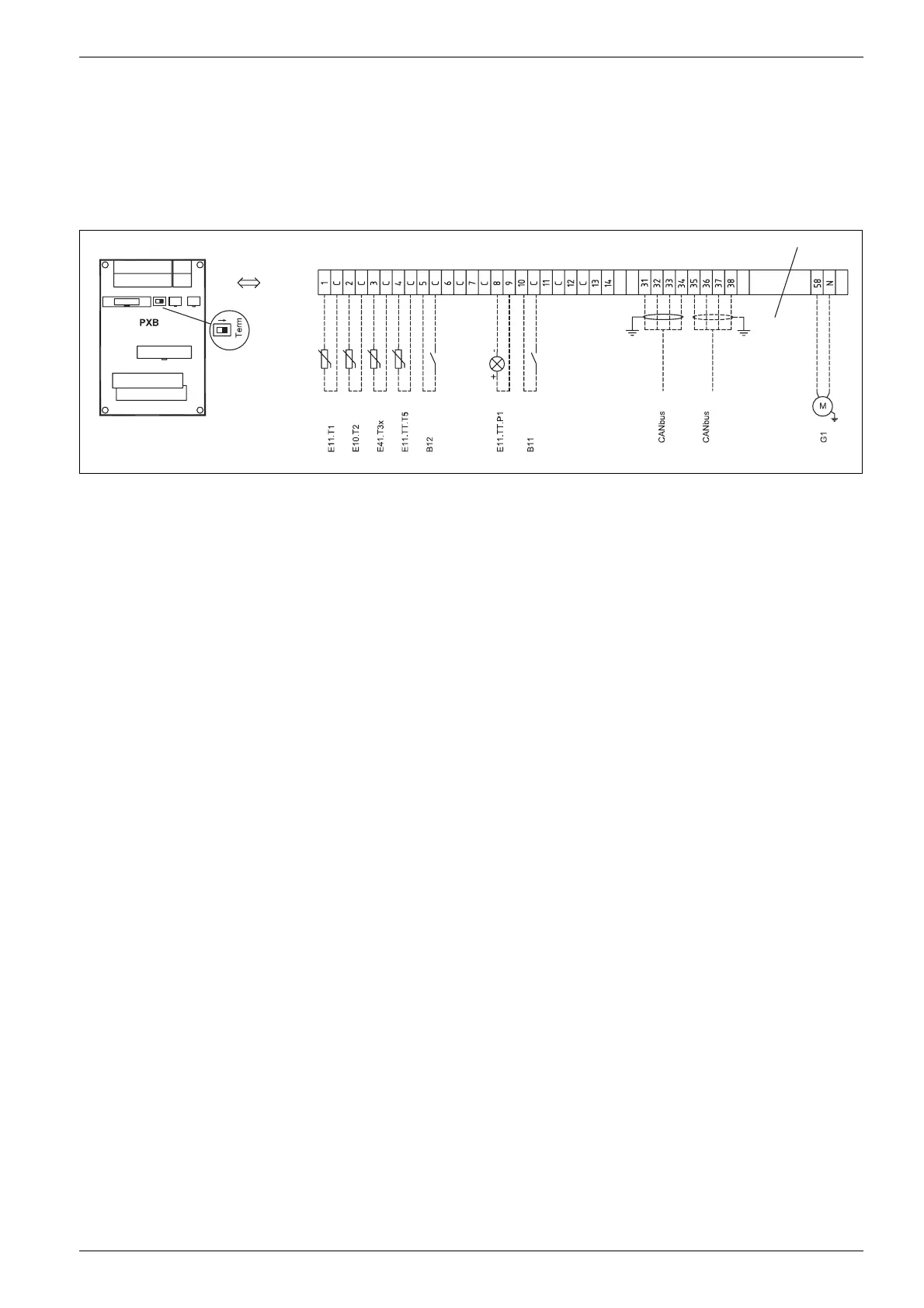
10.5 External connections
All external connections are made on terminal card PXB:
B High and low current cables should be routed
separately in order to avoid interference on the
sensors (minimum distance of 100 mm).
B Use the following cable area when extending the
temperature sensor cable:
– Up to 20 m long cable: 0.75 to 1,50 mm
2
– Up to 30 m long cable: 1.0 to 1,50 mm
2
Fig. 48 External connections
Solid line = always connected
Dotted line = option, alternative:
E11.T1 Flow circuit 1
E10.T2 Outdoor sensor
E41.T3x Hot water E model
E11.TT.T5 Room temperature circuit 1 (not CANbus sensor)
B12 External input 2
E12.TT.P1 LED room sensor, circuit 2
B11 External input 1
E11.G1 Circulation pump circuit 1
6 720 641 570-03.1I