GSXP12HRN
2 – 13
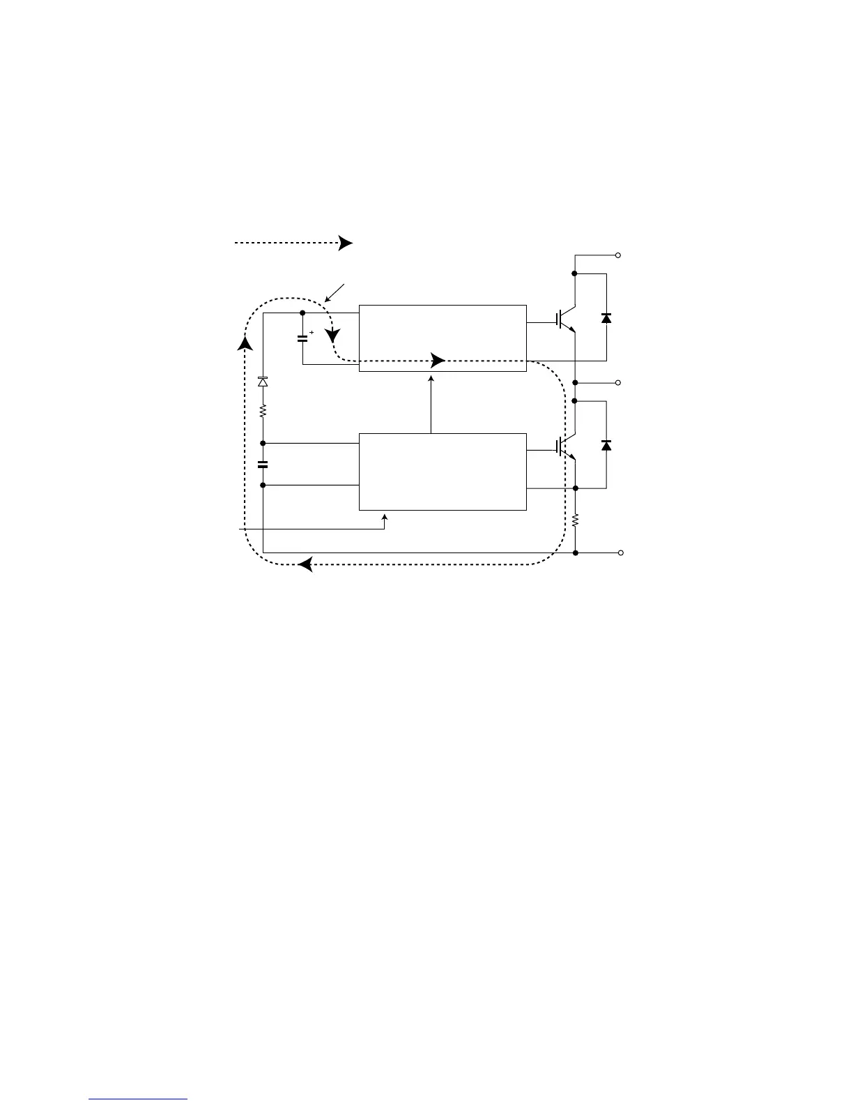
5.1. IPM drive power supply circuit
The power supply for the upper-phase IGBT (HU, HV, HW) drive employs a bootstrap system, and provides power to the upper-phase IC.
The 15-V power supply for the lower-phase IC is provided by the control printed circuit board (PCB).
5.1.1 Brief explanation of bootstrap system (single power drive system)
To supply power to the upper-phase IC, the microcomputer (IC1) turns ON the lower-phase IGBT (LU, LV, LW).
This results in a charging current that flows to the electrolytic capacitor of each upper-phase IC input and charges the bootstrap capacitor with a 15-V
current.
The power supply for the subsequent stages is charged while the lower-phase IGBT is ON in ordinary compressor drive control.
P(Vcc)
U,V,W,
V
D
VDB
VCIN(n)
N-side
IGBT
N(GN
Bootstrap capacitor
High-voltage-withstanding,
high-speed recovery diode
LVIC
(LU,LV,LW)
HVIC
(HU,HV,HW)
Bootstra
circuit
Initial charge period
Charging current group
 Loading...