GSXP12HRN
3 – 3
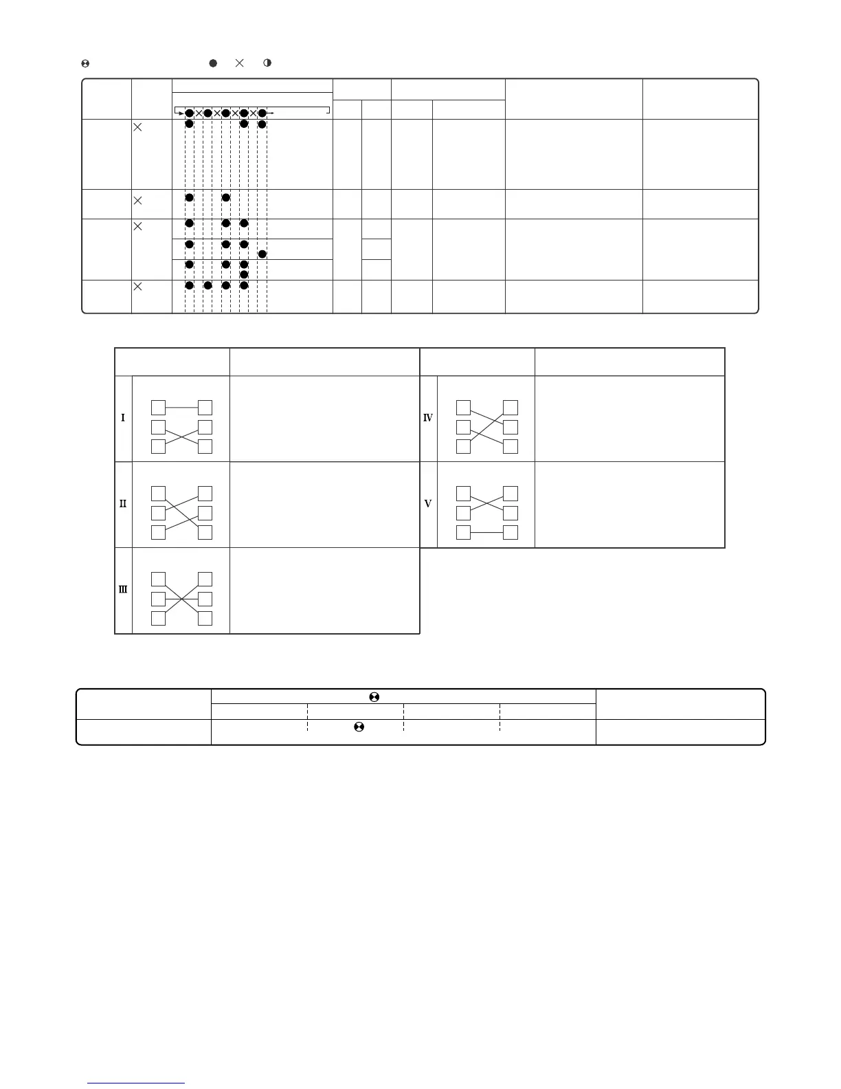
3) In addition to those described above, the following error, which does not result in a complete shutdown, is notified by the flashing LED on the
indoor unit.
Indication by operation lamp on indoor unit
Lighting pattern at the time of timer lamp lighting
Off for 5 seconds
Operation lamp
(RED)
Cluster lamp
(BLUE)
Operation lamp
(RED)
Cluster lamp
(BLUE)
Operation lamp
(RED)
Cluster lamp
(BLUE)
Operation lamp
(RED)
Cluster lamp
(BLUE)
Operation lamp
(RED)
Cluster lamp
(BLUE)
Operation lamp
(RED)
Cluster lamp
(BLUE)
: Flashes in 2-sec intervals (normal), : On, : Off, : Flashes 3 times in 0.2-sec intervals
(When LED1 on the outdoor unit flashes in 2-sec intervals, the outdoor unit is in normal condition.)
Status of
indoor/outdoor
units
Indication by
LED1 on
outdoor unit
*2
Malfunction No.
Content of diagnosis
Inspection location/method Remedy
Main
category
Sub-
category
Main
category
Sub-category
Indoor/outdoor
units in
operation
Indoor unit
control PCB
(EEPROM read data error) (1) Replace the indoor unit control
PCB.
20 -0
EEPROM data error
Indoor/outdoor
units in
operation
Indoor/outdoor
units in
operation
Cluster circuit
Drain pump
unit
(1) Check if the cluster feedback voltage is
proper (0.1 V to 4.9 V).
(2) Check CN5 of the cluster for secure
installation.
(1) Check connector CN2 and CN10.
(1) Replace the cluster unit.
(2) Correctly install CN5 of the
cluster.
(1) Replace the
Drain pump unit
unit.
(2) Re-insertion of CN2 and CN10.
22 -0
30 -0
-1
-2
Cluster voltage error
Drainpumpunit
error
Indoor/outdoor
units in
complete
shutdown
Indoor unit
fan
(1) Check the indoor fan motor for proper
rotating operation.
(Check fan lock.)
(2) Check the lead wire of the indoor fan
motor for open-circuit.
(3) Check CN1 of the indoor unit fan motor
for secure installation.
(4) No abnormality found in above
inspections (1) through (3).
(1) Replace the indoor fan motor.
(2) Replace the indoor fan motor.
(3) Correct the installation of CN1 of
the indoor fan motor.
(4) Replace the indoor unit control
PCB.
19 -0
Indoor unit fan error
Inter-unit wiring
error mode
Indoor
unit
Outdoor
unit
Indoor
unit
Outdoor
unit
Indoor
unit
Outdoor
unit
Indoor
unit
Outdoor
unit
Indoor
unit
Outdoor
unit
Symptom
Inter-unit wiring
error mode
Symptom
1
2
3
1
2
3
1
2
3
1
2
3
1
2
3
1
2
3
1
2
3
1
2
3
1
2
3
1
2
3
Malfunction indications due to erroneous wiring during air conditioner installation
Indoor unit relay Turns On momentarily,
then turns Off.
Malfunction diagnosis display "18-1"
Indoor unit relay Turns On momentarily,
then turns Off.
Malfunction diagnosis display "18-1"
Indoor unit relay Turns On momentarily,
then turns Off.
Malfunction diagnosis display "18-1"
Indoor unit relay Relays turns Off after
about 30 sec.
Malfunction diagnosis display None
(Displays "18-0" when malfunction code
is called out.)
Indoor unit relay Relays turns Off after
about 30 sec.
Malfunction diagnosis display None
(Displays "18-0" when malfunction code
is called out.)
Malfunction
Serial open-circuit error
Malfunction No. (main category)
17 Serial open-circuit error
Flashing LED ( : flashing in 1-sec intervals)
(The Operation and Cluster LED conditions vary based on the equipment operation.)
Operation Timer Cluster (blue) Cluster (green)
 Loading...