FAA Approved Installation Manual for the Report No 908
EDM-900 and EDM-930 Page 18 of 56 Rev I
Primary Engine Data Management System Date 1-18-2013
22. Ammeter Shunt Installation
Use the J5 connector harness 790719-X labeled AMP+ and AMP-. Connect the harness leads using ring terminals
to the smaller terminal screws on the side of the shunt.
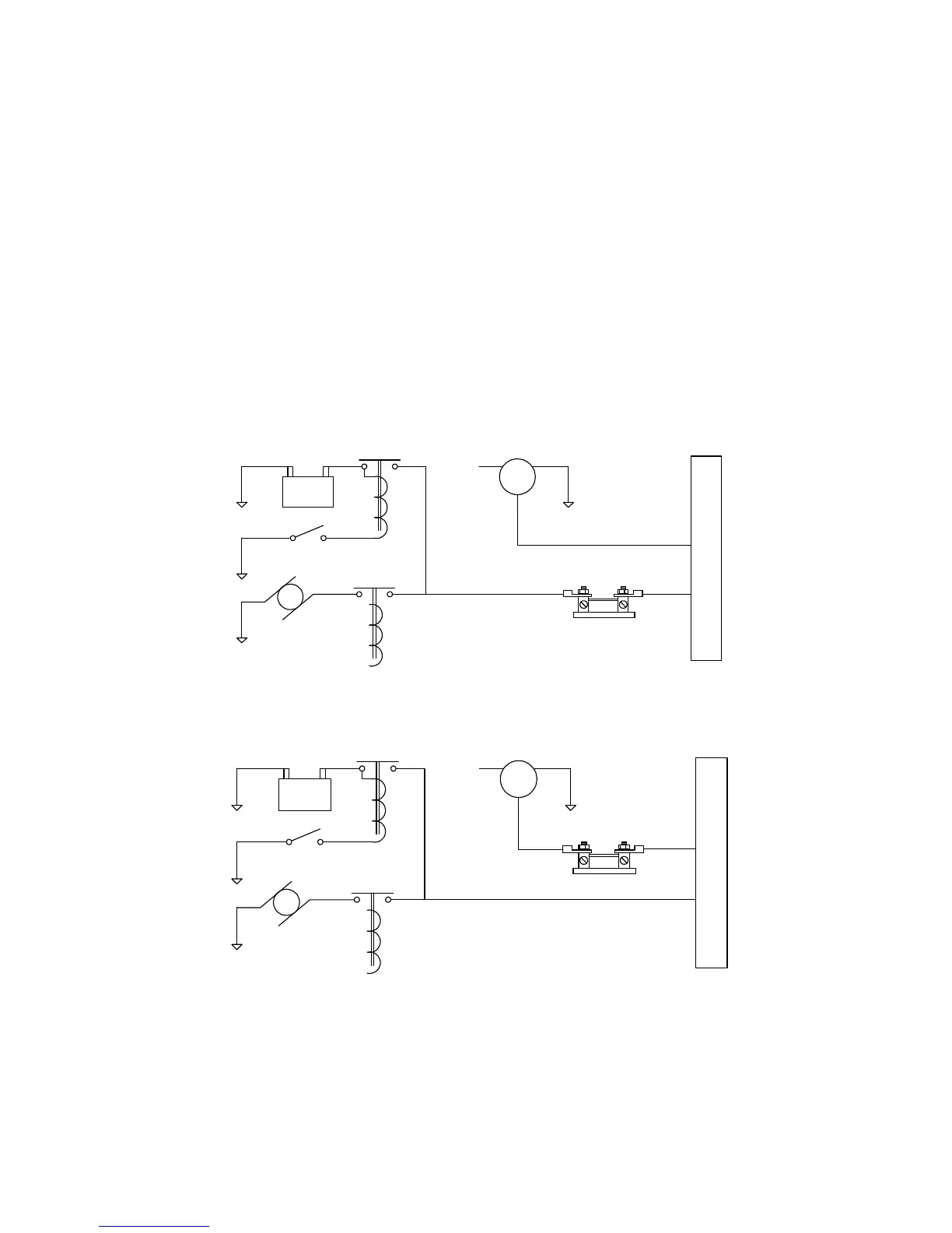
22.1 Charge/Discharge configuration
The shunt can be installed between the master contactor and the main bus in which case it will be in the ammeter
configuration showing battery charge and discharge. Be sure that the positive side of the shunt is connected to the
main bus in the ammeter configuration. The alarm will be triggered by a discharge condition.
- BATT +
Master switch
Starter Starter solenoid
Master switch
contactor
Bus
F G
B
external shunt
Ammeter Configuration
Alternator
+
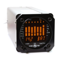
- BATT +
Master switch
Starter Starter solenoid
Master switch
contactor
Bus
F G
B
external shunt
Load Meter Configuration
Alternator
+