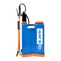
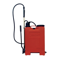
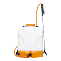
HD-400
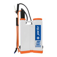
HD-400
LOOSENING ∙ AFLOJAR LA CINTA
∙
Hold the buckle firmly with one hand, and
pull the strap upward with the other hand.
∙
Sujete firmemente el fijador intermediario
de la cinta. Con la otra mano tire la cinta
hacia atrás.
06 19
Attention
∙
Atención
∙ After assembling the sprayer, fill the tank with clean water and pressure-
-check the tank lid, diaphragm, tank bottom, lance and trigger valve
for leakage. Most leaks can be stopped by retightening the appropriate
connections and fittings. Any leakage must be repaired before returning
to service
.
∙ Después de montado, llene el depósito del pulverizador y pruébelo para
eliminar posibles fugas.Conexión de las manguera; diafragma de la tapa;
fondo del depósito; lanza; válvula, etc
.
INVERTING THE LEVER POSITION ∙ ALTERACIÓN EN LA POSICIÓN DE LA
PALANCA
This sprayer is assembled to mount the lever
for left hand operation. In case you wish to
change its position, proceed as follows.
∙ Remove the lock ring (1) and washers (A)
and the rod (2) of the chamber top.
∙ Turn the chamber top 180°. Reinstall the
rod (2) on the chamber top, fit the washers
and secure the rod with the lock ring (1)
again.
∙ Then, remove the lock ring (4 and 5) and
the washers. Remove the lever (6) and the
shaft (7).
∙ Unfasten the strap assembly (8) and mount
it on the other side of the sprayer as shown
in the detail below.
∙ Install the shaft on the other opening on
the tank base; proceed as instructed in the
item 05.
∙ Fit the washers and mount the lever (6) on
the rod oriented to be operated with the
right hand.
El equipo sale de fábrica preparado para
recibir la palanca para accionamiento con
la mano izquierda. En caso de que quiera
cambiar esta posición, proceda de la si-
guiente forma:
∙
Retire la traba de fijación (1), las arande-
las y retire la varilla (2) de la cámara de
compensación.
∙ Enseguida, de un giro de 180º en la cámara
de compensación. Monte la varilla (2) en
la cámara y prenda nuevamente con la
contraclavija (1).
∙ Retire la traba (5), la
traba de fijación
(4 )
y las arandelas. Retire la palanca (6) y el
eje (7).
∙ Retire la cinta (8) y invierta las posiciones
y instale la cinta conforme indica el detalle
en la figura abajo.
∙ Cambie el eje para el otro lado y siga las
instrucciones de montaje del item 05.
∙ Instale las arandelas y monte la palanca en
la varilla para que pueda ser accionada
con la mano derecha.
N.
P/N
DESCRIPTION
Qty
N.
P/N
DESCRIPTION
Qty
LLM-421
ENGLISH
1 1198800 Washers and
lock rings 1
2 907121 Gasket holder and
gasket 1
3 325787 Blue adjustable
cone nozzle 1
4 188250 Chamber (0.23
gallons) 1
5 568535
Piston cup (Viton®
) 1
6 560573 Diaphragm 1
7 1173630 Sphere valve 1
8 635813 Chamber assembly
(includes items 4,
5, 7 and 38) 1
9 920470 Pinch cock 1
10 942193 Nut S-20 x 1.5 2
11 495648
Handgrip with lock
1
12 1197400 Pumping rod 1
13 838029 Strap assembly
(includes 14 to 17) 1
14 1184172 Shoulder strap and
pad 1
15 229971 Strap and handle 2
16 635672 Buckle 2
17 635664 Strap catch 1
18 214619 Agitator 1
19 654939 Cylinder (includes
items 47 and 21
to 25) 1
20 838011 Cylinder valve
assembly (repair)
47, 22 to 25) 1
21 635599 Cylinder body 1
22 715474 Ball 1
23 570945 Ball seat 1
24 336412
Compression spring
12 x 28 1
25 635615 Valve base 1
26 615005 Lever 1
27 293324 Lever shaft 1
28 004739 Lid with diaphragm 1
29 942920 Fill basket strainer 1
30 1211212 Tank 1
31 277350 Shaft lock 1
32 635854 Spray lance 1
33 909192
Trigger valve handle
1
34 909283 Trigger valve body 1
35 105247 Trigger 1
36 908889
Trigger valve assem-
bly 1
37 100131 Extension 601 1
38 48116 Dip tube with hose 1
39 71308 Dip tube assembly 1
40 105239
Trigger valve needle
assembly 1
41 996058 Trigger valve cap
with packing 1
42 909309 Cone packing 2
43 915744 Screw cap 2
44 1149491 Stainless steel tube 1
45 635276 Elbow with cone
packing 1
46 592139 Nozzle filter (40
mesh) 1
47 635607 Piston cup fastener 1