Remove all contents from packaging and inspect to ensure no damage was incurred during shipping. Your USA5 package
should also include the following:
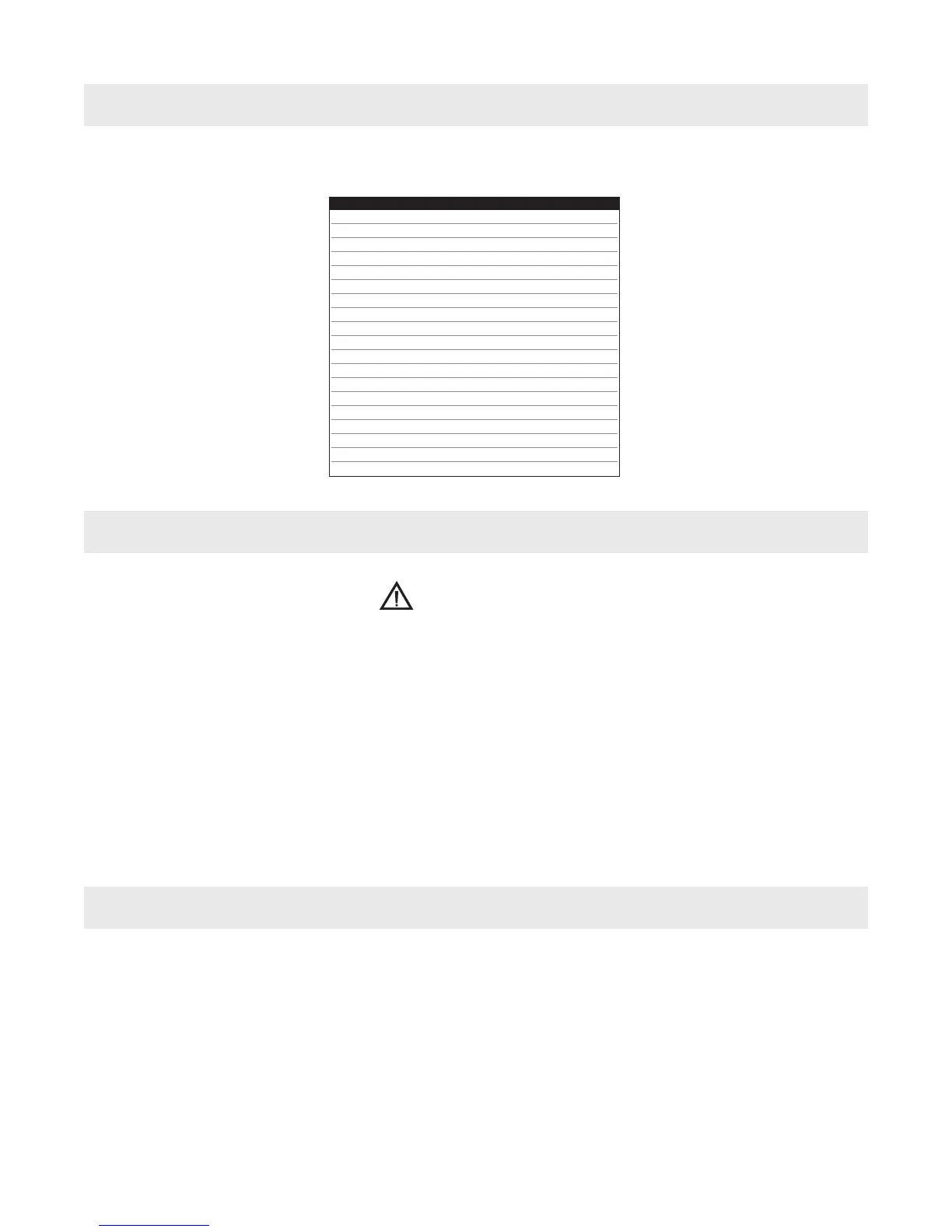
contents of package
description part # qty
OPERATOR'S MANUAL LIT104 1
PRODUCT DVD LIT032 1
WARRANTY CARD 0070342 1
3/16" PILOT, 1" DEPTH OF CUT 16001 1
3/16" PILOT, 2" DEPTH OF CUT 16002 1
1/4" PILOT, 1" DEPTH OF CUT 16003 1
1/4" PILOT, 2" DEPTH OF CUT 16004 1
1/4" PILOT, 3" DEPTH OF CUT 16005 1
3/8-24 X 5/16" FPSSS UH1474 3
3/16" HEX WRENCH UH8013 1
3/16" T-HANDLE HEX WRENCH UH8014 1
4MM HEX WRENCH UH8002 1
SPOKE HANDLE 0151333 3
SAFETY STRAP U11005 1
PIPE HANDLE 0010224 1
PIPE HANDLE ADAPTER 0010225 1
MAGNET WARNING NOTICE 0107D0C 1
SHUNT (ATTACHED TO HANDLE) UH5335 1
SHUNT INSTRUCTIONS U14102 1
getting started
what you should know before you drill
CAUTION!
always disconnect usa5 from power source before making adjustments.
NOTE: The item numbers found below in parentheses refer to the images on page 12.
Assemble three spoke handles (item #18) to hub pinion shaft (item #17). NOTE: Feed hub assembly is mounted on
right side of machine frame . If necessary, it can be reversed for lefthand operation by simply removing the fastener (item
#29) and sleeve (item #30) from frame. Remove hub pinion shaft from right side of frame and insert it into left side of
frame. Replace sleeve and fastener into frame and tighten securely. Thread pipe handle (item #2) into motor housing.
The control panel (item #27) may also be reversed from left to right side of machine if desired. Remove screws (item
#19) holding control panel and side cover plate (item #20) next. Remove side cover plate and control panel, then
disconnect magnet and motor pin connections when removing control panel. Move control panel to opposite side of
frame. Reconnect magnet and motor pin connectors and secure control panel assembly using four screws (item #19).
Replace side cover plate, making sure warning instructions are visible.
1. Type of material to be drilled, Brinnell or Rockwell hardness, material thickness and position should all be determined
to ensure proper selection of Slugger® cutting tools, RPM, coolant and drilling time.
2. Remove any excessive mill scale or rust from surface to be drilled.
3. When drilling materials under 3/8" thick, an additional steel plate may be required to achieve proper magnet
adhesion.
4. Material that has been flame cut may have become heat-treated and therefore difficult to drill. Avoid drilling near
such areas whenever possible.
5. Drilling with the USA5 in horizontal positions requires a special lubrication for Slugger® cutters.
Consult Jancy Engineering for details.
7