Page 10
WARNING
NEVER attempt to assemble,
dis as sem ble or adjust the fi lter when
there is pressurized air in the system.
Starting the pump while there is any
pressurized air in the system can
cause product failure or also cause
the fi lter lid to be blown off, which can
cause death, serious personal injury
or property dam age.
8. While the DE fi lter grid assembly is out of the
fi lter tank, rinse the inside of the tank with water.
Replace drain plug.
9. Gently rinse the grids with water. After cleaning
the fi lter grids, place the grid assembly back into
the fi lter tank bottom (see Sections 6.4 and 6.5 for
further grid cleaning instructions).
10. Replace the tank o-ring and tank lid.
11. Reinstall the tank clamp ring. See Section 3.5 for
tank clamp ring installation.
12. If applicable, open the valves closed in step 4.
5.2 Filter Grid Disassembly/Assembly
1. Remove the complete grid assembly by following
the instructions in Section 5.1, steps 2-6.
2. Remove the manifold by fi rst unscrewing the tie
rod knob in the center of the manifold. Then lift
the manifold assembly off of the grids and the
outlet tube.
3. Remove the top spacer from the grids.
4. The individual fi lter grids can now be removed
from the grid support. Use care to avoid damaging
the grids.
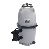
5. See Figure 8 for the arrangement of fi lter grids in
the fi lter grid assembly.
6. To reassemble the fi lter grid assembly, arrange
the fi lter grids into position on the bottom plate
(see Fig. 9). Use the plastic top spacer to hold
the grids in place.
Table 3. Valve Positions for Diverter Valve
Position Function
FILTER Normal filtration and vacuuming.
BACKWASH Cleaning filter by reversing the flow.
RINSE Used after backwash to flush dirt
from the valve.
WASTE Bypasses filter; used for vacuuming
waste or lowering water level.
RECIRCULATE Bypasses filter for circulating water
to the pool.
CLOSED Shuts off all flow to the filter and
pool.
Section 5. Filter Disassembly and
Assembly
5.1 Filter Tank Disassemby/Assembly
1. Backwash fi lter according to the instructions in
Section 6.2.
NOTE Omit this step when fi rst starting a new fi lter.
2. Turn off the pump. Switch off the circuit breaker
to the pump motor.
3. IMPORTANT: Completely open air release valve
on top of the fi lter tank to release all pressure
from inside the tank and system.
4. If the equipment is installed below water level,
close the fi lter isolation valves on the system to
prevent fl ooding.
5. Close the fi lter isolation valves on the system to
prevent fl ooding. Remove the drain plug located at
the bottom of the fi lter tank and allow the tank to
drain.
6. Remove the tank clamp ring from the fi lter and
remove the tank lid. Inspect the tank o-ring for
cracks or tears and replace if necessary
7. Pull the DE fi lter grid assembly out of the fi lter
tank bottom. Use the handles molded into the
manifold to aid lifting.
Figure 9. Filter Grid Ar range ment
JANDY
PN S0109500
OUTLET
PIPE WITH
O-RING
DEL
FILTER
GRID,
SHORT
SPAN
DEL FILTER GRID
(7 REQUIRED)
BOTTOM PLATE
7. Inspect the o-ring at the top of the outlet tube for
cracks or excessive wear. Replace if necessary.
8. Assemble the manifold to the top of the assembly.
Make sure that the grids and outlet tube fi t securely
into the manifold and that the retaining rod extends
up through the hole in the center of the manifold.