Section 2. General Information
2.1 Introduction
This manual contains information for the proper
installation and operation of Jandy
®
Pro Series Valve
Actuators (JVA). Procedures in this manual must be
followed exactly. To obtain additional copies of this
manual visit www.zodiacpoolsystems.com. For address
information, see back cover.
2.2 Description
Valve Actuators are designed to meet the needs of
today's more advanced, automatic pool equipment.
These fully adjustable actuators offer versatile pool/spa
automation with easy setups. All actuators work with
AquaLink
®
RS Control Systems and are available in 24
volt units.
JVA 2444 Specifications
Voltage 24 VAC
Amperage 0.75 AMPS
Cycles 60 Hz
Wire
Black
Red
White
3-conductor
Common
Switch Leg
Switch Leg
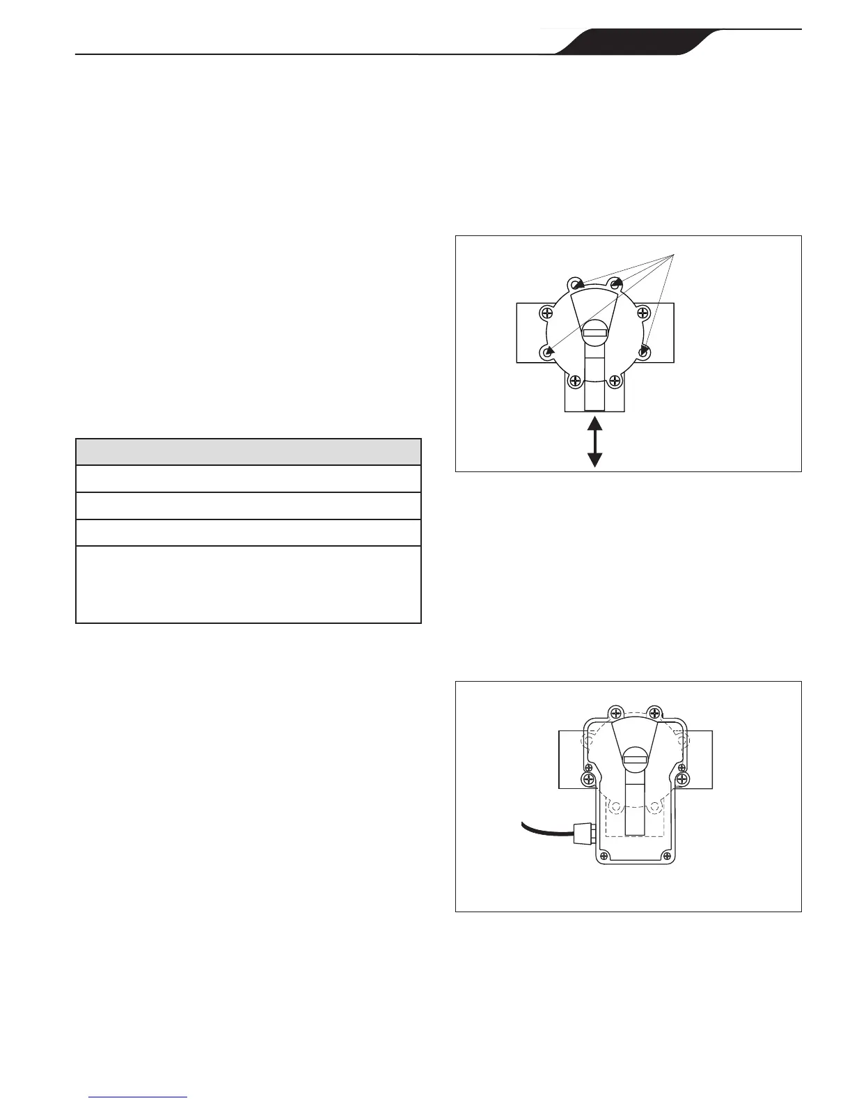
Figure 2. Standard JVA Mounting
A
B (Common Port)
C
A
B (Common Port)
C
Figure 1. Standard Plumbing
Water ow into or
out of the valve
Remove these
four (4) screws for
Standard Position
Section 3. JVA Mounting
Positions
3.1 Standard JVA Position
Standard Plumbing position is with the middle port
(B) as the incoming or common port to the valve (see
Figure 1).
Standard Mounting position is with the main body of
the actuator over port B (see Figure 2).
NOTE If the valve(s) are plumbed with port B as the
common port (Standard Plumbing) and the main
body of the actuator(s) are mounted over port B
(Standard Mounting), there is no need to adjust the
actuator cams.
Page 5
ENGLISH
Jandy
®
Pro Series Valve Actuator
|
Installation and Operation Manual

 Loading...