Jandy
®
VersaFlo
™
Integrated Bypass for JXi
™
& JXiQ
™
Pool and Spa Heater | Installation & Operation Manual ENGLISH
Page 11
4.3 Install New Bypass Assembly
1. Remove the three screws holding the bypass
cover in place.
2. Ensure that the seal is properly seated.
3. Secure the bypass assembly to the header with
sixscrews.
a. Start all six screws by hand.
b. Torque the screws in place following the torque
sequence shown above the note in
Figure 16
.
c. There is an included 5/16" wrench that can be
used to tighten the 2 interior screws. Do not
overtighten!
Section 5. Initial Startup
5.1 Test Bypass Assembly
1. Restore electrical power to the heater and
filterpump.
2. Confirm that the VersaFlo Integrated Bypass is
enabled at the heater.
3. On heater user interface; press and hold the
POOL
,
MENU
and
SPA
buttons
for several seconds (while heater is in standby).
4. The service menu will activate.
Using
scroll to VERSAFLO
BYPASS option.
5. Verify that the bypass option is enabled.
BYPASS
ENABLED
If not, enable the bypass option.
Press
MENU
to exit service mode.
6. Turn on the filter pump.
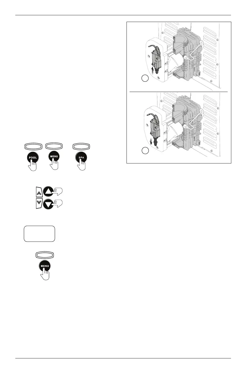
Bypass Gate In Closed Position
Bypass Gate In Open Position
b
a
Figure 17. Bypass Gate and Actuator Positions
7. Inspect for leaks at the bypass header seal and
look for any leaks inside the bypass housing.
8. If no leaks are observed, turn on power to the
heater and activate.
9. Keep the header actuator control in the OFF
(closed) position. Theactuator will be in the down
stroke (extended) position, see
Figure 17 (a)
.
10. Restore gas to the heater.
11. Turn the
header actuator control
in the ON (open)
position, and observe that shortly before the
heater fires, the actuator will move
to the up stroke
(open) position. See
Figure 17 (b)
.
12. Turn the heater off. After approximately a one-
minute delay the actuator will return to the down
position (OFF). See
Figure 17 (a)
.
13. After completing all of the steps to test the bypass
accessory and confirming correct operation,
replace the bypass housing cover using three (3)
screws.