Page 8
ENGLISH
Jandy
®
VersaFlo
™
Integrated Bypass for JXi
™
& JXiQ
™
Pool and Spa Heater | Installation & Operation Manual
3.2 Route Wire Harness
3.2.1 JXi Heater
NOTE: The new VersaFlo is equipped with the JXiQ wiring
harness. Before installation on a JXi heater it will be
necessary to replace the wire harness on the new
VersaFlo with the included JXi wire harness.
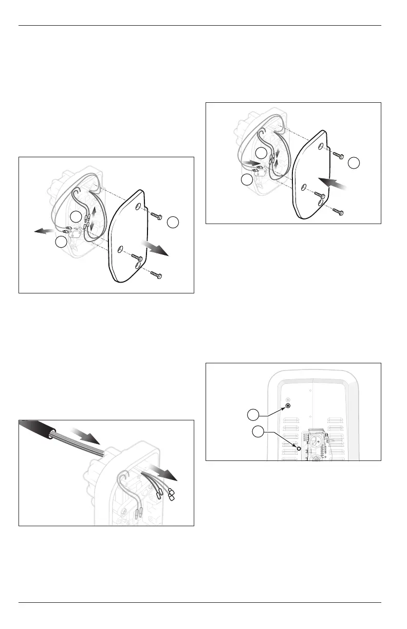
1. Remove the three screws holding the bypass cover
in place on the new VersaFlo, see
Figure 7 (a)
.
2. Disconnect the two pink wires from the
microswitch, see
Figure 7 (b)
.
3. Disconnect the blue and green actuator wires,
see
Figure 7 (c)
.
c
b
a
Figure 7. VersaFlo Remove JXiQ Wiring
4. Pull out the two microswitch wires and the two
actuator wires through the opening in the back
of the VersaFlo one at a time without damaging
grommet, set the JXiQ wire harness aside.
5. Examine the new JXi harness electrical
connectors and wires to ensure that none of the
wires or connectors are damaged or abraded.
6. Feed the wire terminal end of the two pink
microswitch wires and the two green and blue
actuator wires from the new JXi wiring harness
through the opening in the back of the VersaFlo
one at a time, see
Figure 8
.
Figure 8. Install JXi Wiring
7. Connect the blue and green wires to the blue and
green actuator wires in the new VersaFlo, see
Figure 9 (a)
.
8. Connect the two pink wires to the microswitch in
the new VersaFlo, see
Figure 9 (b)
.
9. Secure the bypass cover on the new VersaFlo
using the three screws, see
Figure 9 (c)
.
c
b
a
Figure 9. Connect Microswitch and Actuator Wires
NOTE: Make sure the pink microswitch wires and the green and
blue actuator wires are not pinched by the bypass cover
on the new VersaFlo when tightening.
10. Pass the wire terminal end of the two pink wires
and the green and blue wires from the new JXi
wiring through the electrical orifice on the side
panel. See
Figure 10 (a)
. If using the low voltage
knockout you may need to remove the cap and
replace with the included knockout bushing, see
Figure 10 (b)
.
NOTE: If your heater serial number is revision “G” (GXXXXXX)
orearlier you will need to use the low voltage knockout
towire the heater, see
Figure 10 (b)
.
Low
Voltage
Knockout
Electrical
Orifice
a
b
Figure 10. JXi Electrical Orifice
11. Route the wire along the interior of the heater and
behind the high voltage raceway.
12. Secure at raceway brace corner using the installed
P-Clamp or the zip ties included with the kit.
13. Route through the standoff along center of the
raceway brace. If no standoff is installed please
secure with zip ties.
14. Pass the harness through the grommet at the low
voltage raceway, see
Figure 11 (c)
.