Jandy
®
VersaFlo
™
Integrated Bypass for JXi
™
& JXiQ
™
Pool and Spa Heater | Installation & Operation Manual ENGLISH
Page 5
Section 3. Electrical Connections
Before beginning the installation or replacement of the
VersaFlo Integrated Bypass the following steps must
betaken.
a. All power to the heater and filter pump must
be disconnected at the breakers.
b. The gas supply to the heater must be shut off.
c. (Optional) The water can be drained from the
heater by removing the drain plug (drain plug
& outer temp sensor on JXiQ models) at the
header. See
Figure 2
.
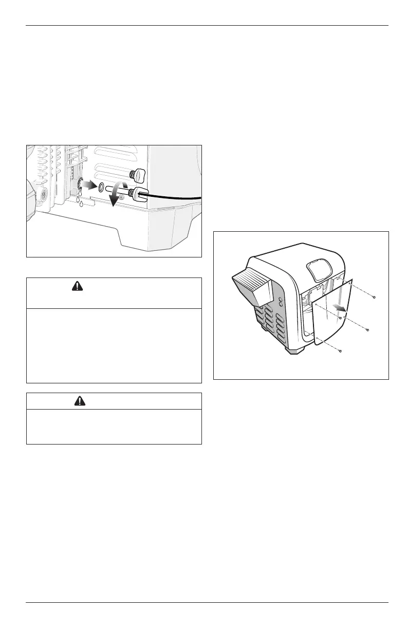
Figure 2. Drain Header
WARNING/
SHOCK HAZARD
Follow all applicable installation codes. Prior to
installation or performing any service, turn off all
switches and the main breaker in the pool/spa pump
electrical circuit. Failure to comply may cause a shock or
hazard resulting in severe personal injury or death. While
disconnecting and/or connecting any electrical wiring,
becareful not to damage or abrade any of the wiring.
WARNING
In order to prevent the risk of fire or electrocution, all
electrical power and gas supply to the heater must be
disconnected.
3.1 Open the Heater
1. Remove the screws holding the front heater panel
in place to expose the raceway. See
Figure 3
.
2. Locate the raceway lock release label on the
interior of the heater raceway.
3. Cut the zip tie to release raceway. See
Figure 4 (a)
.
4. Using a screwdriver or comparable tool; press into
the raceway release orifice until the raceway latch
releases and the raceway swings free. See
Figure
4 (b)
.
5. Swing the raceway up into a horizontal position.
See
Figure 4 (c)
.
6. Latch raceway into position using the bracket.
See
Figure 4 (d)
.
7. Remove the 4 screws holding the top cover in
place. See
Figure 5
.
8. Remove the top cover being mindful not to
damage or strain the user interface wiring.
See
Figure 5
.
NOTE: Some heater
models may require
the removal of 6 or 8 screws.
Figure 3. Remove Front Panel