Jandy
®
VersaFlo
™
Integrated Bypass for JXi
™
& JXiQ
™
Pool and Spa Heater | Installation & Operation Manual ENGLISH
Page 9
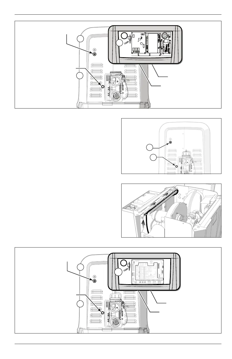
Low Voltage Knockout
b
a
Electrical Orifice
PCB
Low Voltage
Grommet
c
Figure 11. JXi Bypass Harness Routing
3.2.2 JXiQ Heater
1. Examine the electrical connectors and wires to
ensure that none of the wires or connectors are
damaged or abraded.
2. Feed the electrical harness through the electrical
orifice on the side panel. See
Figure 12 (a)
. If using
the low voltage knockout you may need to remove
the cap and replace with the included knockout
bushing.
NOTE: If your heater serial number is revision “G” (GXXXXXX) or
earlier you will need to use the low voltage knockout to
wire the heater. See
Figure 12 (b)
.
3. Route the wire along the interior of the heater and
behind the high voltage raceway. See
Figure 13
.
4. Secure at raceway brace corner using the installed
P-Clamp or the zip ties included with the kit.
5. Route through the standoff along center of the
raceway brace. If no standoff is installed please
secure with zip ties.
6. Pass the harness through the grommet at the low
voltage raceway, see
Figure 14 (b)
.
Low
Voltage
Knockout
Electrical
Orifice
b
a
Figure 12. JXiQ Electrical Orifice and Voltage Knockout
Figure 13. Bypass Harness Routing
R Kit # R0984000
1 2 3 4
5
6
7
8
111317181920
21
22
23
25
24
26
27
28
30
29
16 14 15 12
10
9
1 Fuse
2 Ignition Control LED
3 RS-485 LED
4 User Interface LED
5 User Interface
6 Blower
Only provide external power to items 7, 11 & 12.
7 Power Input
5A @120/240VAC
8 Igniter/Flame Strength
9 Igniter
5A @120VAC
10 Transformer
11 Louver
12 Auxiliary
13 Spa 3 wire
14 Com 2 wire / 3 wire
15 Pool 2 wire / 3 wire
17 Flue Temp
18 Outlet Temp
19 Inlet Temp
20 Gas Valve
21 Gas Pressure Switch
22 Air Pressure Switch
23 Louver Switch
25 High Limits Switch
24 Auxiliary
Switch
26 Water Pressure
Switch
27 VersaFlo
™
Switch
29 24 VAC R
28 VersaFlo
™
Actuator
30 24 VAC Y
Ignition Timing Sequence:
Pre-Purge: 15 secs
Heat Up: 40 secs
Ignition: up to 7 secs
Inter Purge: 15 secs
Post Purge: 45 secs
Lockout will occur after
3 successive failed
ignition attempts.
H0774700_REVB
24 VAC, 50/60 Hz
16 RS-485
CAUTION
HIGH VOLTAGE DISCONNECT
WIRING BEFORE SERVICING
Input Power: 120/240 VAC (5A)
24 VAC (3A), 50/60Hz
Ambient: 0°F(-18°C) to 176°F(80°C)
UL 60730-1, UL 60730-2-5
CSA E60730-1, CSA C22.2 No. 60730-2-5
Low Voltage Knockout
a
Electrical Orifice
PCB
Low Voltage
Grommet
b
a
Figure 14. JXiQ Bypass Harness Routing