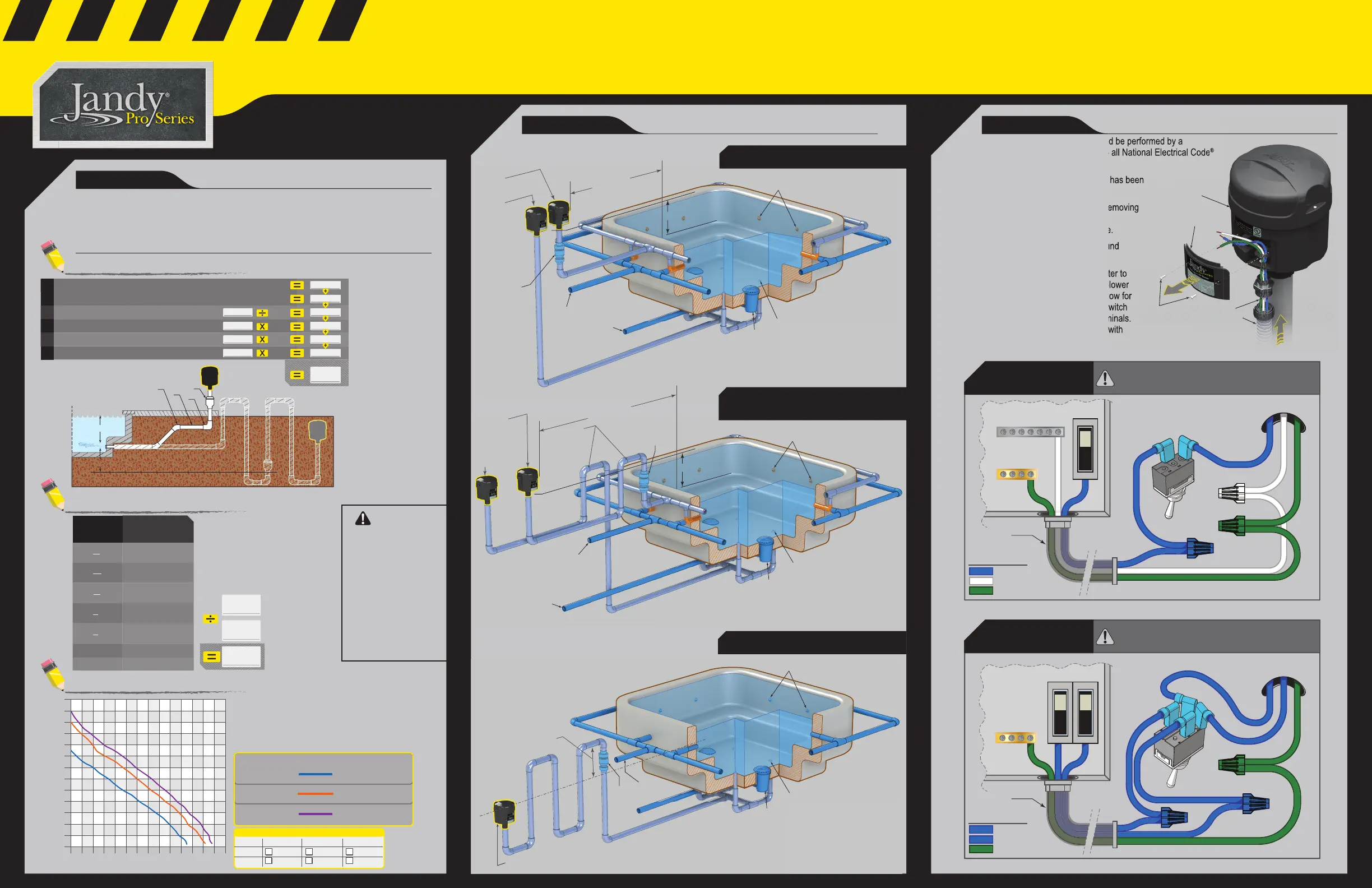
Correctly sizing the blower for your application is a critical step to the sustained operational quality
of your Jandy Pro Series Pool and Spa Blower. Damage or failure due to an improperly sized
blower is not covered under warranty.
SIZING WORKSHEETS: The worksheets below will guide you through the proper sizing
calculations for your application.
1. SELECT BLOWER
2. PLUMBING 3. WIRING
Vertical Measure from Pool/Spa surface to air outlet
Number of feet of 2” Pipe
Number of 90° Elbows
Number of 45° Elbows
Number of 1/2 lb check valves
Total Back Pressure
(Inches of Water)
Calculate Back Pressure
4
a
b
c
d
e
Vertical Measure from air outlet to lowest check valve (See Note)
a
1
10
.5
.125
Calculate back
pressure as a measure
of “inches of water”.
Verifi cation of this
fi gure can be made by
using a manometer.
AIR HOLE
SIZE
CONVERSION
FACTOR
Calculate Airflow
1
″
8
5
″
32
3
″
16
1
″
4
3
″
8
1.2
″
0.15
0.1
0.27
0.6
1.1
1.5
2.4
Jet
Total Airflow
SCFM
(Standard Cubic Feet Per Minute)
Conversion
Factor
No. of Holes
Air Flow Rate (SCFM)
Pressure H
2
0 10 20 30 40 50 60 70 80 90 100 110 120 130 140
10
0
20
30
40
50
60
70
80
90
100
110
120
Performance Curves (60 HZ)
Models: PSB110
Models: PSB115
Models: PSB120
Max Back Pressure 40"
Max Back Pressure 50"
Max Back Pressure 65"
Models: PSB210
Models: PSB215
Models: PSB220
Voltage
Blower Selection
120V
1.5 HP 2.0 HP1.0 HP
PSB110
PSB115 PSB120
240V
PSB210 PSB215 PSB220
Determine Blower Needed
Choose an air hole size from
the chart at left and apply the
conversion factor in the formula
below to determine total airfl ow in
standard cubic feet per minute.
Installation of this equipment should be performed by a
licensed electrician and conform to all National Electrical Code
®
(NEC
®
), state and local codes.
1. Ensure all power to the blower has been
disconnected at the main breaker.
2. Remove blower front door by removing
the two (2) screws sliding the door
downward and pulling the door free.
3. Pull in voltage source and ground
wire from Power Center.
4. Connect wires from power center to
the corresponding wires from the blower
motor. Use the wiring diagrams below for
reference. The 120 or 240 toggle switch
will come preinstalled with fl ag terminals.
Connections will need to be made with
Wire nuts.
WARNING
Installing an insuffi ciently
sized blower will
increase back pressure.
Failure to accurately
follow the blower
sizing calculations
provided could result
in excessive back
pressure. Excessive
pressure can cause
damage that could result
in electrocution causing
severe injury or death.
Water Line
Water Line
Air Line
Check Valve*
Spa Return
To Pump
Sump
to water level
12” min.
5’ - 25’
min.
max.
Bubbler Jet
Venturi Jet
†
Blower
(installation with
Venturi Jets
†
)
Blower
(installation with
Bubbler Jets)
* Install a 1/2 lb. U.L. listed check valve between the
blower and the jets to prevent water damage to the blower.
Ensure that check valves are accessible for servicing.
†
Do not install adjustable jets. These may cause
excessive back pressure.
ON
OFF
Line 1
Neutral Bus Bar
Ground Bus Bar
From Blower Motor
From Power Center
Power Center
120V Toggle Switch
Flex Conduit
120V Wiring
RISK OF ELECTRIC SHOCK WHICH CAN RESULT IN SERIOUS
INJURY OR DEATH. Before attempting installation, ensure that all
power to the device is disconnected/turned off at the circuit breaker.
Be careful not to damage or abrade any wiring or other components.
LEGEND
Line 1
Neutral
Ground
ON
OFF
Line 2
ON
OFF
Line 1
Ground Bus Bar
From Power Center
Power Center
Flex Conduit
From Blower Motor
240V Toggle Switch
LEGEND
Line 1
Line 2
Ground
240V Wiring
RISK OF ELECTRIC SHOCK WHICH CAN RESULT IN SERIOUS
INJURY OR DEATH. Before attempting installation, ensure that all
power to the device is disconnected/turned off at the circuit breaker.
Be careful not to damage or abrade any wiring or other components.
Water Line
Air Line
Check Valve*
Sump
Spa Return
to water level
12” min.
Over 25 Feet
Hartford loop
Plumb as
close to the
pool/spa wall
as possible.
Bubbler Jet
Venturi Jet
†
* Install a 1/2 lb. U.L. listed check valve between the blower
and the jets to prevent water damage to the blower.
Ensure that check valves are accessible for servicing.
†
Do not install adjustable jets. These may cause excessive
Blower
(installation with
Venturi Jets
†
)
Blower
(installation with
Bubbler Jets)
LONG RUN INSTALLATION
(over 25’ from spa wall)
STANDARD INSTALLATION
Installation of this equipment should be performed by a
licensed electrician and conform to all National Electrical Code
Ensure all power to the blower has been
Remove blower front door by removing
downward and pulling the door free.
Pull in voltage source and ground
Connect wires from power center to
the corresponding wires from the blower
motor. Use the wiring diagrams below for
reference. The 120 or 240 toggle switch
will come preinstalled with fl ag terminals.
Connections will need to be made with
Screw
Conduit
Wires
Blower Door
Blower
From
Power Center
2” min.
water
level
Check
Valve*
Sump
Bubbler Jet
Blower
Water Line
Air Line
Spa
Return
To
Pump
* Install a 1/2 lb. U.L. listed check valve between the
blower and the jets to prevent water damage to the blower.
Ensure that check valves are accessible for servicing.
Hartford Loop -
To install the
blower below
water level, or if
the blower air
line drops
below the
bottom of the
spa, use the
Hartford Loop
plumbing
configuration to
prevent the air
line from filling
with water.
BELOW GRADE INSTALLATION
a
a
1
Spa
Deck
Grade
Blower
e
d
b
c
NOTE: Include a
1
for
installations with a check
valve below the air outlet
only. See “Below Grade
Installation” on facing page
for details. For above grade
installations enter 0 for a
1
.
Locate the total back pressure, calculated above
and draw a horizontal line. Locate the total airfl ow
from previous step and draw a vertical line. These
lines will intersect on the performance curve of the
minimum HP blower required for your application.
 Loading...