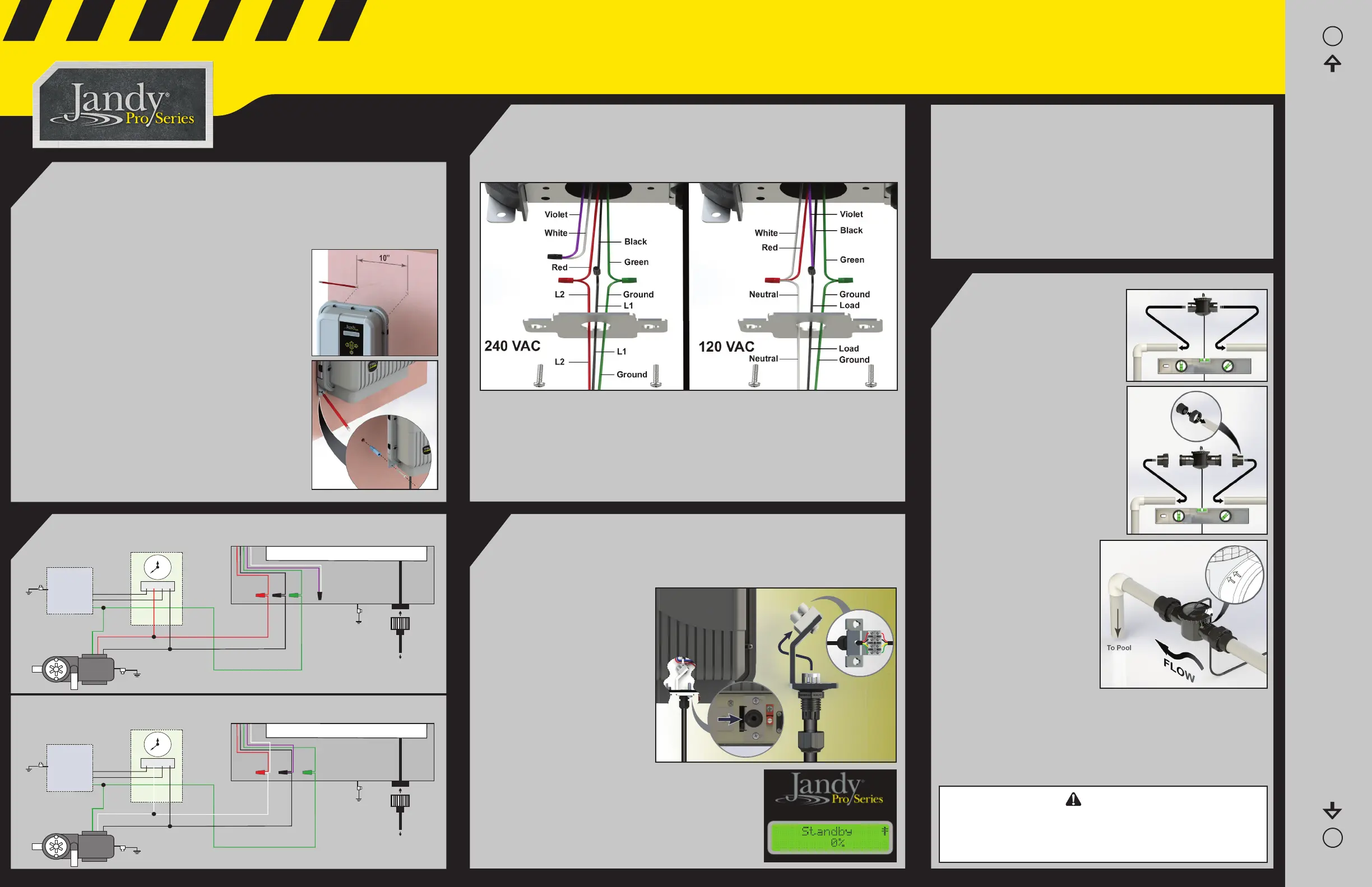
Wiring the Power Pack to the Power Source
1. Run 12 AWG (3.3 mm
2
) insulated wire and fl exible conduit from the LOAD
side of the pool pump timer/automation relay so that the TruClear will only
receive power when the pool pump is turned on. See Wiring Diagram.
2. Remove 2 screws lock washers and the electrical mounting plate.
3. Feed power cable through the mounting plate, and connect the conduit to the
mounting plate.
4. Make the wire connections.
5. Place all of the wire connections and cables inside the power pack and secure
the mounting plate tightly.
6. Plug the cell into the power pack.
3
2
← Top Left Mounting Indicator
Power Pack Mounting Template
Use this template to drill holes for mounting the power pack
Top Right Mounting Indicator
→
Installing the Power Pack
REFER TO OWNER’S MANUAL FOR PROPER INSTALLATION. IMPROPER
INSTALLATION AND/OR OPERATION WILL VOID THE WARRANTY.
1. Install at least 2 feet (0.6 m) above the ground. Protect from water spray and
mechanical impact. Keep out of reach of children. Consult and comply with
all applicable local and national installation codes
and/or regulations, as may be enforced by local
Authorities Having Jurisdiction (AHJ’s) or Competent
Authority.
2. Install the power pack a minimum of 5 feet (1.5 m)
in the US, 10 feet (3 m) in Canada, from the inside
wall of your pool or spa.
3. The center distance between holes is 10 inches.
Use a level and the template at right in order to
locate the exact position of the holes.
4. Drill holes and install wall anchors and screws.
5. Hang the Power Pack from the top two keyholes on
the backplate.
6. With the power pack in place, mark the position of
the bottom two holes.
7. Remove the power pack, drill the bottom two holes
and install the wall anchors.
8. Hang the power pack from the top two screws and
drive in the bottom screws.
1
5
Use Copper Conductors Only – Rated for 90°C Minimum
Pool Pump
TO EARTH BONDING POINT
POWER PACK
POOL PUMP TIMER
3
12
6
9
240 VAC
CIRCUIT BREAKER
PANEL
TO CELL
GROUND
LINE 2
LINE 1
BLK
GRN
VIOLET
WHITE
L 1
L 2
GROUND
RED
TO EARTH
BONDING POINT
Use Copper Conductors Only – Rated for 90°C Minimum
Pool Pump
TO EARTH BONDING POINT
POWER PACK
POOL PUMP TIMER
3
12
6
9
120 VAC
CIRCUIT BREAKER
PANEL
TO CELL
GROUND
NEUTRAL
LINE 1
BLK
GRN
VIOLET
WHITE
LOAD 1
NEUTRAL
GROUND
RED
TO EARTH
BONDING POINT
Installing the Cell
1. Install the cell as the last
piece of equipment before
the return inlet to the pool.
2. Install on a pipe segment at
least 16 inches long, which
runs within ± 5º of level
(parallel to the ground). The
cell must not be mounted on
a vertical, or sloping pipe.
3. The cell must be mounted
upright with view window
facing up.
4. Cut the PVC pipe to
accommodate the cell. The
removed segment will be
6 inches for a standard
installation (no threaded
unions) and 14.5
inches for the retrofi t
installation (with
threaded unions).
5. Remove the cell from
the housing.
6. Using properly rated
PVC cement, plumb the
housing into the pipe,
making sure that the
fl ow indicator arrows on
the housing match the fl ow direction of the water. Pipes
must be clean and dry before gluing.
7. Let the system dry per instructions provided by the PVC
cement manufacturer. When the cement is dry, start the
system and check for leaks and confi rm correct water fl ow
direction.
7. Once connection has been made, the User Interface (UI)
should display “Standby ‡”.
8. Follow the instructions for your automation system to
continue with device set up and schedules.
9. Once proper communication is confi rmed, reinstall the
RS485 connector bracket into the power pack body.
10. If proper communication is not established begin with
step 3 and retrace the above steps.
11. If communication is still not established please call
technical support at 800-822-7933.
240 Wiring Diagram - Use Copper Conductors Only - Rated for 90º C Minimum
120 Wiring Diagram - Use Copper Conductors Only - Rated for 90º C Minimum
4
3
Install RS485 for Jandy Automation
The power pack comes equipped with a slide out RS485 connector. The
RS485 connector is used to connect the Jandy TruClear chlorination system to
a new or existing AquaLink
®
Automation System.
1. Loosen DO NOT REMOVE
the two screws securing the
RS 485 connector bracket
in place.
2. Slide out and expose the
4 pin RS485 connection
terminal.
3. From an open auxiliary on
your automation system
run the RS485 cable to the
4 pin RS485 connection
terminal.
4. Unscrew cable fi tting nut,
pass RS485 wires through and re secure nut.
5. Pass wires through center slot on bracket.
6. Use a small fl at head screwdriver to install the
wires from the automation system. Match the
colors to the wires already installed from the
power pack.
WARNING
The Jandy Pro series chlorine generating electrolytic cell must be
installed outdoors only. The cell must be installed horizontally with the
cord facing upwards to avoid buildup of flammable gases, which can
result in FIRE or EXPLOSION

 Loading...