2+3)0R
d. While holding the aligned face ring assembly and
d. While holding the aligned face ring assembly and
fixture together, turn the assembly upside down
fixture together, turn the assembly upside down
and set it on the old gasket, using the old gasket
and set it on the old gasket, using the old gasket
as an assembly fixture. This will keep the lens and
as an assembly fixture. This will keep the lens and
gasket assembly from being pushed out of the face
gasket assembly from being pushed out of the face
ring while you secure it to the light fixture.
ring while you secure it to the light fixture.
e. Spread the bottom clamp over the electrical cord
e. Spread the bottom clamp over the electrical cord
and slide it onto the back of fixture to the top
and slide it onto the back of fixture to the top
clamp.
f. Tighten the Phillips head screws (eight (8) for
f. Tighten the Phillips head screws (eight (8) for
large light and six (6) for small light) on the color
large light and six (6) for small light) on the color
light in alternating cross-pattern. Torque screws to
light in alternating cross-pattern. Torque screws to
approximately 20 in-lbs. Do not over-tighten.
approximately 20 in-lbs. Do not over-tighten.
g. Discard the old gasket.
g. Discard the old gasket.
7. Reinstall the Jandy Light into niche xture.
a. Coil the extra four (4) feet of cord around the
a. Coil the extra four (4) feet of cord around the
fixture or into the base of the niche and place the
fixture or into the base of the niche and place the
light assembly into the niche.
light assembly into the niche.
b. Engage the retainer tab on the bottom of the face
b. Engage the retainer tab on the bottom of the face
ring, then pivot the top of the fixture inward and
ring, then pivot the top of the fixture inward and
tighten the special pilot screw.
tighten the special pilot screw.
WARNING
a=)0./<G0,8)0=()D-+<0(-<.,0=D*)V0(*.M-:):0V-,80,8-=0
C/:)*V+,)*0<-38,5078-=0=D*)V0K.C/,=0+/:0)<)D,*-D+<<G0
3*.C/:=0,8)08.C=-/30=)DC*)<G0,.0,8)0K.C/,-/30*-/30
+/:0V),0/-D8)50L+-<C*)0,.0C=)0,8)0=D*)V0(*.M-:):0
D.C<:0D*)+,)0+/0)<)D,*-D+<08+Y+*:S0V8-D80D.C<:0*)=C<,0
-/0:)+,80.*0=)*-.C=0-/ZC*G0,.0(..<0.*0=(+0C=)*=S0
-/=,+<<)*=0.*0.,8)*=0:C)0,.0)<)D,*-D+<0=8.D[5
8. If pool is empty, ll the pool until the underwater
light is completely submerged in water before
operating the light for more than 10 seconds. Turn
on main switch or circuit breaker, as well as the
switch, which speci cally operates the underwater
light, to check for proper operation.
WARNING
W)M)*0.()*+,)0,8-=0C/:)*V+,)*0<-38,0@.*0K.*)0,8+/0
6"0=)D./:=0C/<)==0-,0-=0,.,+<<G0=CNK)*3):0-/0V+,)*50
H-,8.C,0,.,+<0=CNK)*=-./S0,8)0<-38,0+==)KN<G0V-<<03),0
)T,*)K)<G08.,S0V8-D80K+G0*)=C<,0-/0=)*-.C=0NC*/=0.*0-/0
:+K+3)0,.0,8)0<-38,5078-=0K+G0*)=C<,0-/0=)*-.C=0-/ZC*G0
,.0(..<0.*0=(+0C=)*=S0-/=,+<<)*=S0.*0NG=,+/:)*=0.*0-/0
:+K+3)0,.0(*.()*,G5
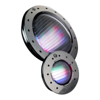
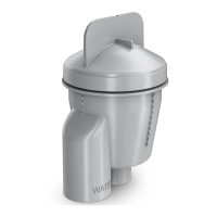
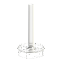
Figure 5. Alignment of the Lens, Face Ring, Housing and Clamps for Color Lights
&<-3/0+**.V0.@0,8)0
<)/=0V-,80,8)0(-<.,0
=D*)V
&<-3/0(-<.,0=D*)V0V-,80
,8)0+**.V0<.D+,):0./0
,8)00T,C*)0<+N)<
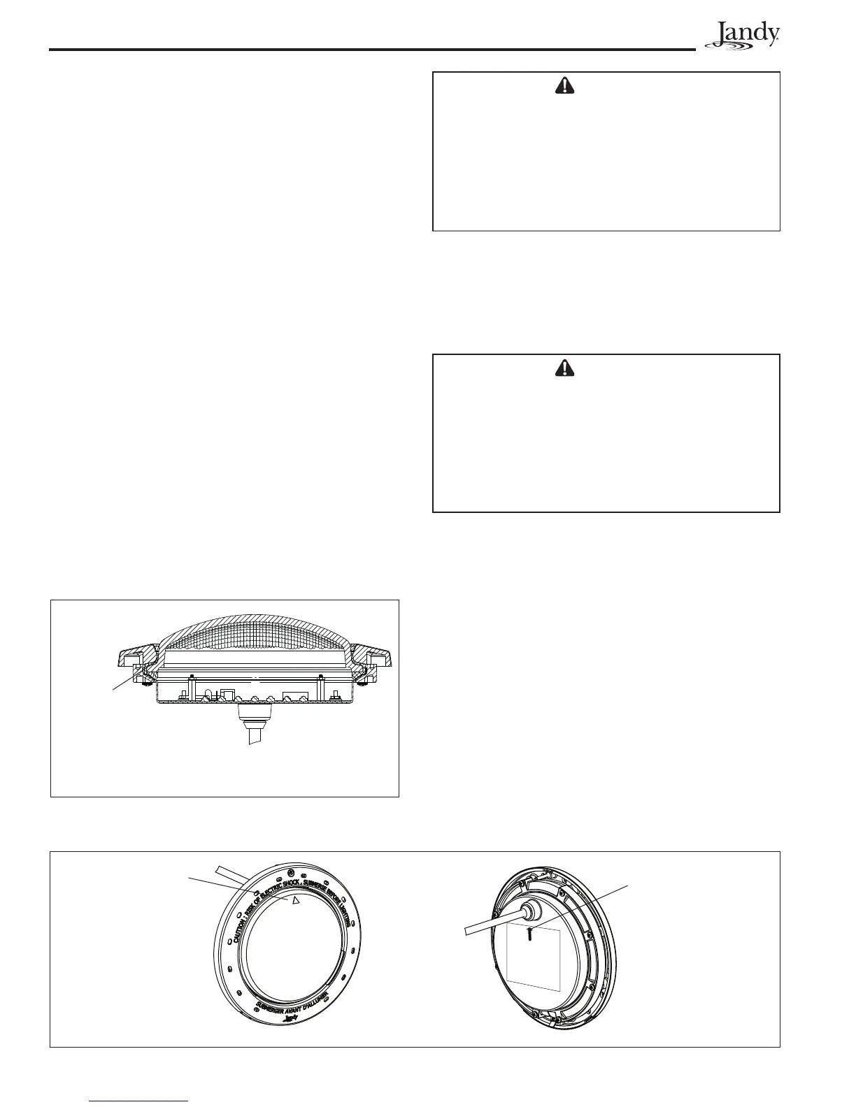
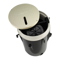
Figure 4. Cross Section of Jandy WaterColors LED
Light
78-D[0K.<:):0
=-:)0.@0,8)0
3+=[),0KC=,0
K+,)0V-,80
,8)0N.:G0.@0
,8)08.C=-/3