Installationsanvisning Janfire Flex - a
IA Brännare Flex-a R2 SV
Janfire 2009
11(19
)
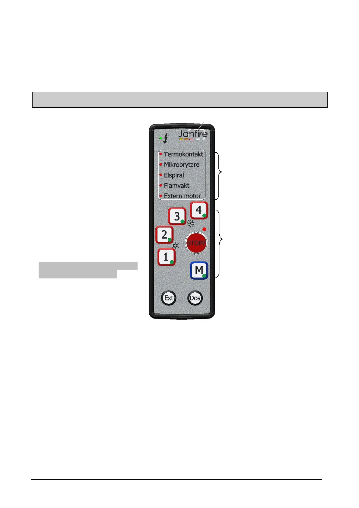
3.2 Control panel
Functional description of the control unit. Explanation of the light signals and burning status
Note: Work with electrical parts of the plant should only be performed after the main fuse has disconnected,
and only by qualified personal
STOPP = stopp/stand by
4 = 18 kW power
3 = 15 kW power
2 = 12 kW power
1 = 9 kW power
M = Manuell operation (15 kW)
Note !!! Ext Dos buttons can only
be activaded in Stop Mode
Ex t= Manuel operating of extern
motor
Dos = Manuel operating of
dosing motor
Power indication
Alarm diodes
Operating indication
Indication of diodes operating:
In each button for each power option there's a LED that can light up yellow, green or both yellow
and green.
When one of the power buttons activates lights diodes as follows:
Yellow and green ignition progress
Yellow and flashing green ignition progress-electric coil active
Green – Combustion running
Figur 4 Control panel