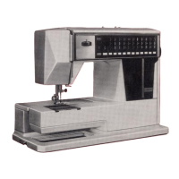
Do you have a question about the Janome 5030 and is the answer not in the manual?
Procedure for removing and attaching the face cover.
Procedure for removing and attaching the free-arm cover.
Procedure for removing and attaching the front cover.
Procedure for removing and attaching the rear cover.
Adjusting the distance between presser foot and needle plate.
Setting the needle's position relative to the needle plate hole.
Aligning the rotary hook with the needle's travel for correct timing.
Adjusting the height of the needle bar for proper sewing operation.
Setting the gap between the needle and the rotary hook tip.
Setting the highest position of the feed dog for fabric feeding.
Adjusting the upper thread tension for optimal sewing quality.
Balancing the feed mechanism for stretch stitch patterns.
Procedures for replacing and adjusting the needle threader plate.
Adjusting the buttonhole lever and sensor positions for accuracy.
Details on connecting various components to Printed Circuit Board A.
Procedure to remove and attach Printed Circuit Board A.
Procedure to remove and attach Printed Circuit Board F2.
Procedure to remove and attach Printed Circuit Board F1.
Procedure to remove and attach Printed Circuit Board L.
Procedure to remove and attach the DC motor.
Procedure to remove and attach the switching regulator unit.
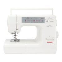
| Type | Mechanical |
|---|---|
| Stitch Options | 30 |
| Maximum Stitch Width | 5 mm |
| Maximum Stitch Length | 4 mm |
| Needle Positions | Variable |
| Foot Control | Yes |
| Needle threader | Yes |
| Speed control | Yes |
| Start/Stop Button | Yes |
| Speed | 860 stitches per minute |