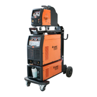
2.1.5 Welding unit
Controller
Table 2-2 Definition of controller wiring
Connected to the -15V port of ±15V switching
power supply
Connected to the COM port of ±15V switching
power supply
Connected to +15V port of ±15V switching
power
Connected to the V- port of 24V switching power
supply
Connected to the V+ port of 24V switching
power supply
24V output voltage, providing 24V to the serial
port display together with
Air pressure alarm signal input port; To enable
(requires wiring), set the "Air Pressure Alarm
Level" on the display screen settings page to be
consistent with the actual air valve alarm level
used.
Water tank alarm signal input port; if required to
be enabled (the wiring is required), set the
"Water Cooler Alarm Level" on the display
screen settings page to a value consistent with
the actual water cooler alarm level used.
Connected to the workpiece, forms a loop with
 Loading...