17
OPERATION - MIG
Before starng any welding acvity ensure that you have suitable eye protecon and
protecve clothing. Also take the necessary steps to protect any persons within the welding
area.
MIG/MAG welding mode
MIG - Metal Inert Gas Welding, MAG - Metal Acve Gas Welding, GMAW - Gas Metal Arc Welding
MIG welding was developed to help meet producon demands of the
war and post war economy which is an arc welding process in which a
connuous solid wire electrode is fed through a MIG welding gun and
into the weld pool, joining the two base materials together.
A shielding gas is also sent through the MIG welding gun and protects
the weld pool from contaminaon which also enhances the arc.
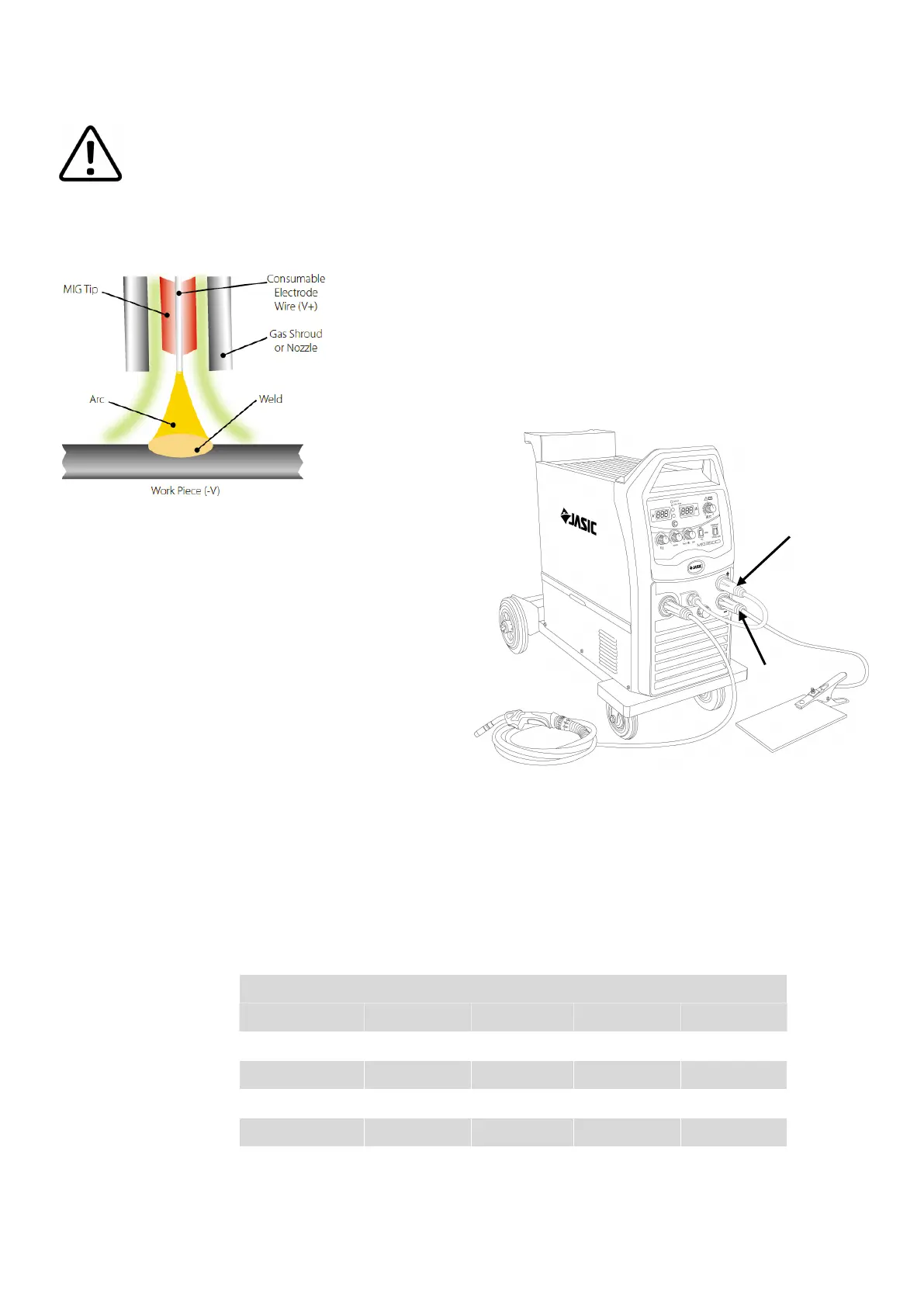
Connect the MIG torch leads as detailed on page 15.
Work return lead to ‘-’ (B) and torch trailing lead to
‘+’ (A).
Ensure that a suitable inert gas supply is connected.
Switch the power switch on the back panel to “ON”
the machine is started with the power LED on and the
fans are running.
Switch the MMA/MIG switch to MIG mode (ensuring
the standard/spool gun switch is set to standard).
Open the gas valve of the cylinder and adjust the gas
regulator to obtain the desired ow rate.
Adjust the “voltage control knob in MIG” and “wire feed speed control knob in MIG” on the front panel of
the machine to get the correct welding voltage and welding current. Operate the torch trigger and
welding can be carried out.
Where required adjust the burn-back me potenometer (above the feed unit inside the machine) to get
the proper wire sck-out. One second aer the arc stops, the gas supply will be cut o.
The MIG wire guide below can vary depending on material used, work piece thickness, welding posion
and joint form.
MIG - Gasless
The operaon method is the same as the above MIG operaon except there no shielding gas is used and
the output polarity is reversed (see page 15).
Wire Diameter DIP Transfer Spray Transfer
(mm) Current (A) Voltage (V) Current (A) Voltage (V)
0.6 30 ~ 80 15 ~ 18 n/a n/a
0.8 45 ~ 180 16 ~ 21 150 ~ 250 25 ~ 33
1.0 70 ~ 180 17 ~ 22 230 ~ 300 26 ~ 35
1.2 60 ~ 200 17 ~ 22 250 ~ 400 27 ~ 35
1.6 100 ~ 280 18 ~ 22 250 ~ 500 30 ~ 40
A
B
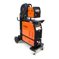
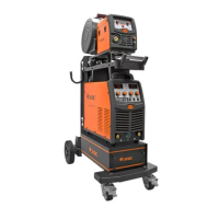
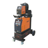
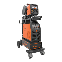
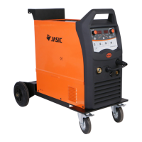
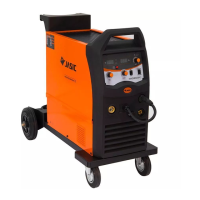
Model shown as example is the JM-352C
 Loading...