Diagram: Distribution box connection (for reference)
Wiring diagram of distribution box
1 Power switch of distribution box
2 Fuse of 60A or more.
3 Welder cable: Single-phase 230V, copper cable of
3*4
or more is adopted.
4 Olivine ground wire (connected to GND! instead of null
line), copper cable of 4
or more is adopted;
Wiring should be conducted with main power off as shown in
the diagram or in other correct ways.
Attention: Do not operate with power!
Connection to be done by professional electrician.
Do not connect two welders to the same fuse box.
If enclosure is connected to GND, wire 4 is not
connected to GND!
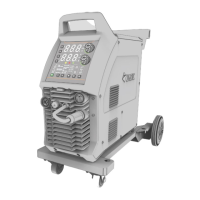
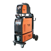
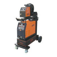
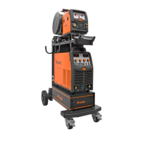
7.1. Installation
7.1.1. Power cord installation: Welder power cord is connected to 50Hz/60Hz AC grid via fuse of 60A or
more.
7.1.2. Ground wire connection: Cable plug with earth clamp is inserted into the “-” socket at the bottom of
the front panel and is tightened.
7.1.3. Gas pipe connection: One end of gas pipe is connected to gas port on the back panel, while the
other is connected to gas cylinder through gas meter.
7.1.4. Heater power connection: Heater power plug on the gas cylinder is inserted into heater power
socket on the back panel.
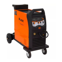
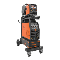
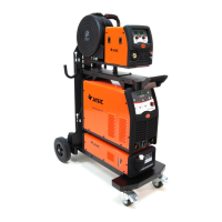
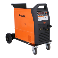
7.2. Installation diagram and instruction
 Loading...