4.2 Electrical connection
Attention:
1. All electrical connection has to be carried out by qualified and licensed operators.
2. Please turn off the distribution box switch and make sure safety before any electric connection.
3.Please use required standard cables.
4.Don’t touch with wet hands.
5.Don’t place heavy items on cables.
6.Tap water pipe, house rebar may be in poor ground condition. Please don’t use them as safe ground lead.
7.Every welder is equipped with an air switch or fuse.
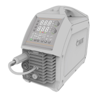
4.3 Front & back panel introduction
Fig 4.1
Front panel description:
1. Digital front panel(parameters selection,
setting and display.)
2. Wire feeder control cable connector
3. Quick socket for positive output (connect wire
feeder or MMA electrode holder)
4. Quick socket for positive output(connect
MMA earth clamp)
Back panel description:
1. Breaker(air switch)
2. Wire feeder control cable connector
3. Software upgrade interface
4. 3 phase power cable(4×6mm
2
/4×4mm
2
)
5. Socket for gas heater (Not for any other use
except heating gas )
6. Quick socket for positive output(connect wire
feeder)
7. Cooler interface
 Loading...