CONFIGURATION AND CALIBRATION –Software Config.
Page 57 of 80
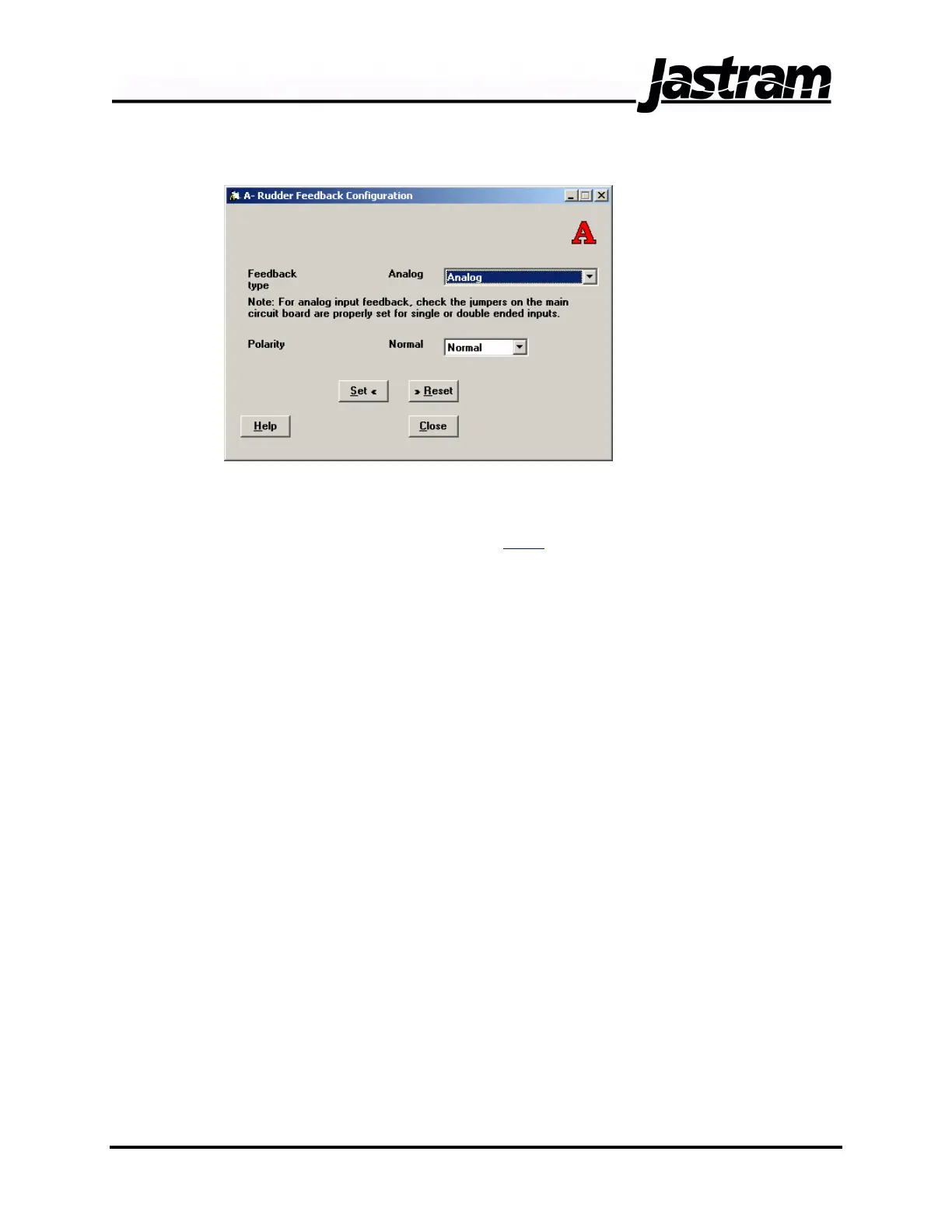
Rudder Feedback Configuration Window
Two drop down lists
allow for the
selection of the
Feedback Type and
Polarity of the
rudder feedback
signal. The
available feedback
types are Analog
and Resolver.
Normally this setting
is left as Analog
which will
accommodate both single ended potentiometer type inputs as well as
double ended or differential type feedback signals. Be sure to set the
jumpers on the DSC circuit board for the correct single ended or double
ended analog inputs (see section 1.3.2
).
The Polarity drop down list allows for the selection of Normal or Reverse
polarity of the rudder feedback signal. If the rudder feedback direction
displayed on the first line of the DSC’s LCD screen does not correspond
with the actual direction of the steering gear then the polarity can be
swapped to correct this condition. This condition is normally checked
once the system is connected to the feedback of the steering gear to be
controlled.
Select the appropriate setting from the drop down lists. When finished,
click the SET button before clicking the CLOSE button.
Doc No.: MAN01504, 20-02-06 DSC 100 & MCP 100 Manual