59
The Power Gear® Slim Rack slideout is typically used
for slideouts 144” long and longer.
It is operated by a 12VDC electric motor.
The system is equipped with a manual over-
ride allowing the room to be extended / retract-
ed in the event of a power loss.
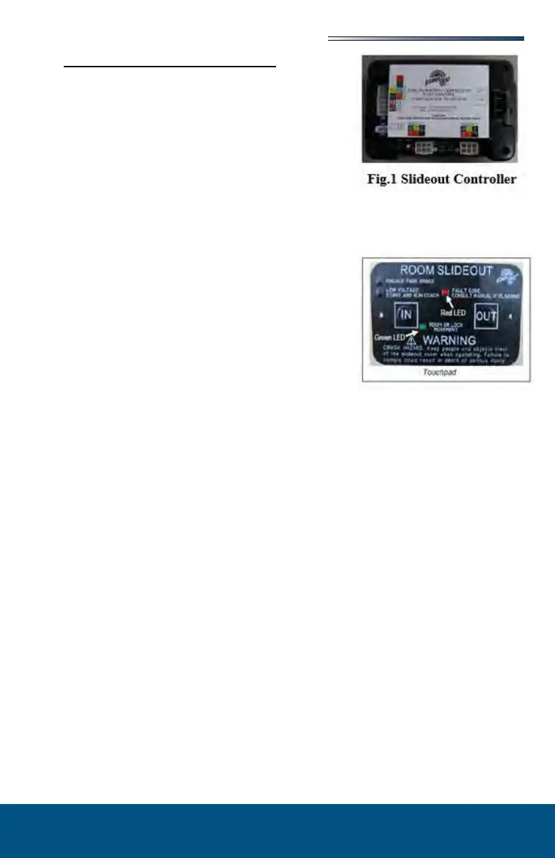
The system has a controller (Fig 1) with pro-
grammable stops that stop the motor when the
room is fully extended or retracted.
The controller has the ability to detect faults
for easier troubleshooting.
A wall mounted touchpad allows room movement and provides end user feedback.
The slideout will not function until the stops are properly
set or faults are cleared.
indicates room movement.
with the
system. (Refer to the Fault Diagnostics / Troubleshoot-
ing).
To ensure ample voltage is being supplied to the slideout
system motor, power should be supplied from one of the following sources:
Attach the RV to shore power.
Have the motor home engine running.
Turn on the generator.
1. Engine or generator must be running, or plugged into shore power.
2. Transmission must be in park or neutral (if applicable).
3. Set the parking brake and level the unit.
4. Remove transit bars (if so equipped) if extending the room; install if retracting.
5. Turn the on/o switch or key.
6. Press and hold the OUT button. To retract, press and hold the IN button. There will be
a slight delay before the room begins moving.
7. The GREEN LED should be solid ON when room is in motion.
8. Release the OUT button when the room is fully extended or the IN button when fully
retracted, and stops moving.
9. Turn the on/o switch or key.
The control has the ability to detect and display several faults. When a fault is detected,
room movement stops and two dierent LEDs will ash in a pattern.
The RED FAULT CODE LED will ash a number of times corresponding to a specic fault
code (refer to the Fault Code Chart).
The GREEN ROOM MOVEMENT LED will ash GREEN a number of times correspond-
ing to which motor has the associated fault.
Example: (4) RED ashes and (2) GREEN ashes indicate a motor fault on motor 2.