SPECS
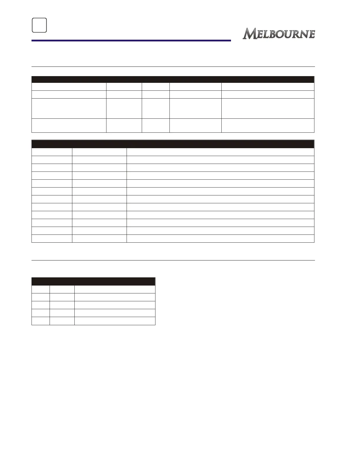
DC FUSE PANEL LAYOUT
Below is a typical wiring layout. Your individual motorhome may be different.
ITEM AMP SIZE TYPE APPLICATION LOCATION
Remote Mirrors 1 Glass Option In line under dash - left hand side
Back-up Monitor 1.5 Glass Option In line under dash - left hand side
Power Step/Auxiliary Start
Switch/Auxiliary Start
Solenoid
5 Blade Standard Under das - left hand side
Dash radio memory/
auxiliary start
5 Blade Standard On battery disconnect solenoid
12-volt DC Layout
1 30 amp Tank heater #1/bedroom slideout motorh
2 15 amp Bath area, tank heater switch
3 15 amp Monitor panel/kitchen area/water pump
4 15 amp Furnace/rear roof vent
5 15 amp Bed area
6 15 amp 12-volt outlets/overhead cabinet lights
7 15 amp Living area/porch/bunk lights
8 15 amp Trunk lights/power awning
9 15 amp Main slideout lights/rangehood
10 15 amp Front roof vent/dinette light
11 15 amp Refrigerator/slideout switch/propane detector/dash radio
12 30 amp Tank heaters #2 & #3/main slideout motor
CIRCUIT BREAKERS
The following table provides generic circuit breaker alignment information. Your RV may not be exactly
the same as shown depending on model, floor plan and options.
Main 30 amp Main, incoming power to unit
A 15 amp Refrigerator, GFCI, kitchen/bath
B 15 amp Utility/converter/inverter
C 20 amp Air conditioner
D 15 amp Water Heater
E 15 amp Convection microwave
96
SECTION 10
SPECIFICATIONS & GLOSSARY