Amplifier Power
Tne
maximum recommended power
input
to tne low frequency
loudspeakers is 200
W
continuous sine wave at an Impedance
of 4 n. and 100 W contiruous sire wave at 8 n
into
the
high
freouency section Larger amplifiers car be employed
U
normal
precautions against
input
device
distortion
or amoifier clipping
are
followed
Component Removal
To
optimize the sound dispersion characteristics of the
loudspeaker
system,
maintain tne acoustical
integrity
of tne
enclosure and facilitate inspection and service
ah
components
mount
directly to tne baffle pane! and are removable
from
the
front
ol the enclosure
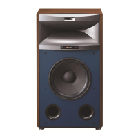
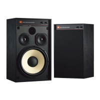
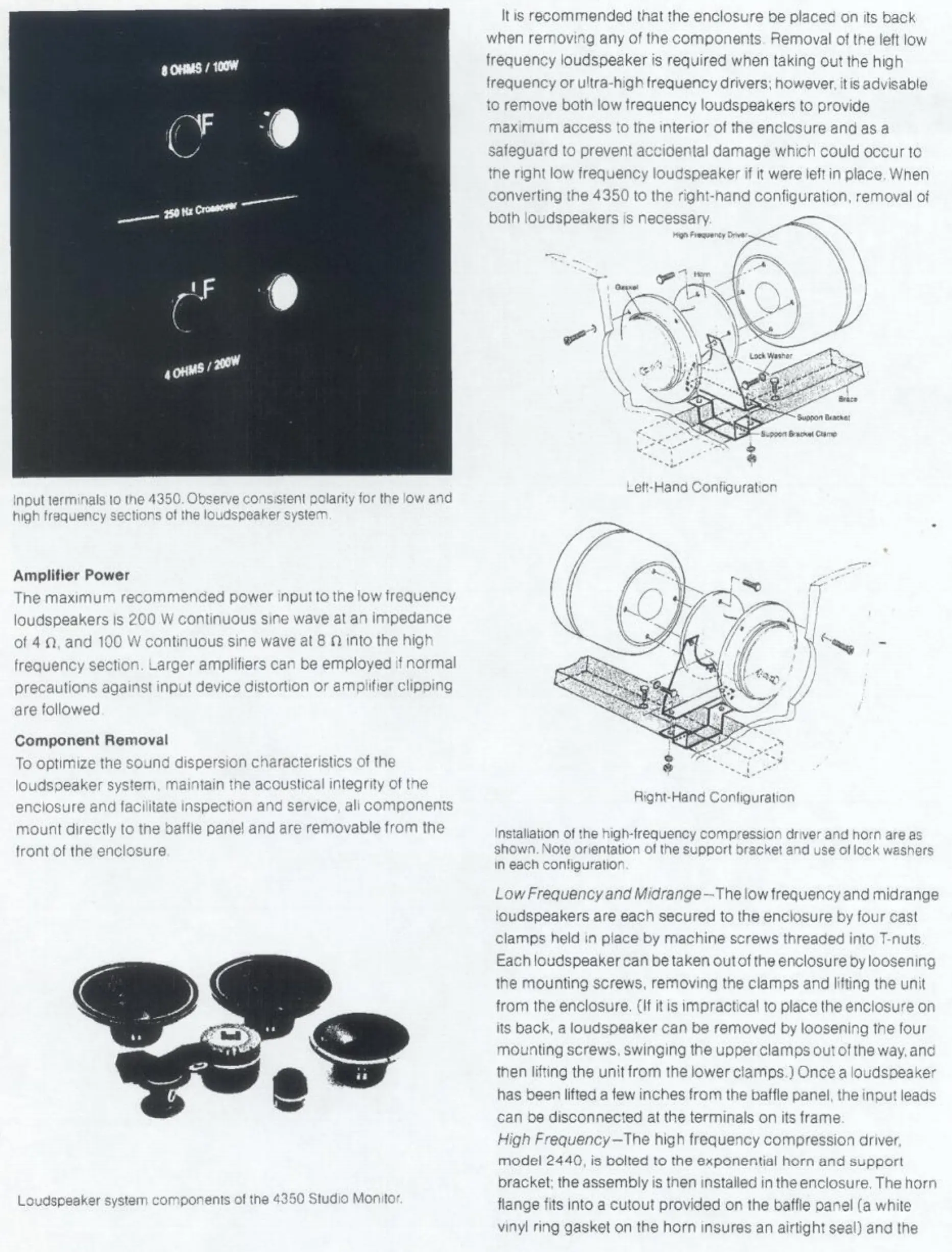
Loudspeaker system components ol the 4350 Studio
Monitor.
It is recommended mat the enclosure be placeo on its back
when removing any of the components Removal of the
left
low
frequency loudspeaker is required when taking out the
high
frequency or ultra-high frequency
drivers;
however, it
is
advisable
to remove
both
low frequency loudspeakers to provide
max,mum
access
to tne
interior
of the enclosure and as a
safeguard to prevent accidental damage whicn could occur to
tne
right
low frequency loudspeaker if it were
left
in place. When
converting the 4350 to the nght-nand configuration, removal of
both
loudspeakers is
necessary.
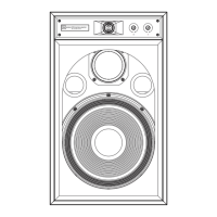
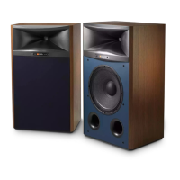
Lett-Hano
Configuration
Right-Hand
Configuration
Low
Frequency
and
Midrange-The
low frequency and mid range
loudspeakers are eacn secured to the enclosure by
four
cast
clamps
held in place by machine
screws
threaded
into
T-nuts
Each
loudspeaker
can
be taken
outof
theenclosure
Oy
loosening
the
mounting
screws,
removing the clamps and
lifting
the
unit
from
the enclosure. (If it is impractical to place the enclosure on
its back, a loudspeaker can be removed by loosening the
four
mounting
screws,
swinging the upper clamps out of tne
way.
anc
then
lifting
the
unit from
the lower clamps ) Once a loudsoeaker
has
been
lifted
a few inches
from
the baffle panel, the
mout
leaas
can
oe disconnected at the terminals on its frame.
High
Frequency-the
high
frequency compression driver.
model 2440, is
bolted
to the exponential horn and support
bracket; the assembly is tnen installed in theenclosure. The horn
flange fits
into
a
cutout
provided on the baffle oanel fa white
vinyl
ring
gasket on the horn insures an
airtight
seal)
and the
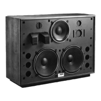
input
terminals to tne 4350. Observe coisisieni
polarity
tor the iow and
high
frequency sections ot the loudspeaker system.
installation of the high-frequency comp'ession driver and now are as
shown.
Note
orientation
ot the
support
oracket a-id use ot lock washers
m each
configuration.
 Loading...