22
FINAL LOW FREQUENCY FILTER
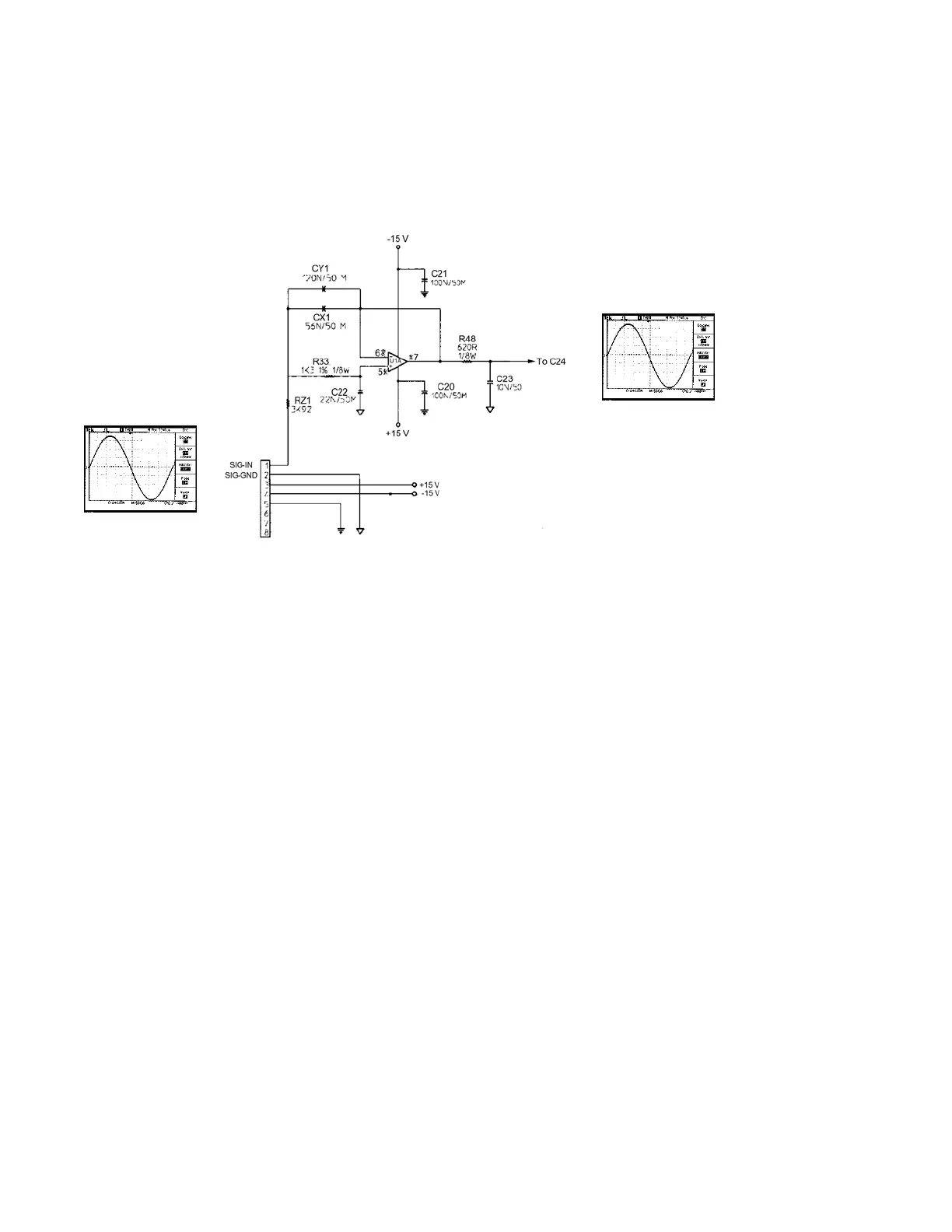
The two-pole active Butterworth low pass filter, shown above, is situated on the main
PCB board. Circuit-wise, it is located immediately before entering the main low frequency
amplifier. It effectively removes any ultra high frequency noise that might have slipped by the
main filtering or been induced in the interface input cabling after the main filtering and
attenuates that signal at a rate of -40 dB after the critical frequency. The circuits main purpose is
to verify that only low frequencies are passed on to the low frequency amplifier reducing the
possibility of damage to the low frequency transducer. It has a first order filter consisting of R21
in combination with the total capacitance of CX1 and CY1, and a second order filter using R33
and C22.The critical frequency for this filter can be calculated using the equation:
Critical Frequency = 1/{(2π)(R1R2C1C2)1/2} where R1 = R21, R2 = R33
C1 = CX1, C2 = CY1
= 1.467 kHz
In
ut= .95V
100 Hz
Ou
ut= .95 V